
12vdc to 37v dc converter

The circuit described is a DC to DC converter designed to convert an input voltage of 12V DC to an output voltage ranging from 0V to 37V DC. This circuit utilizes the SG3524 integrated circuit, which is a versatile PWM (Pulse Width Modulation) controller. The SG3524 is capable of driving external power transistors to achieve the desired voltage levels.
The circuit operates by first generating a PWM signal that controls the duty cycle, which in turn regulates the output voltage. The input voltage is fed into the SG3524, where it is compared against a reference voltage. The output of this comparison adjusts the PWM signal, which is then used to drive a switching transistor or MOSFET. This transistor rapidly switches on and off, allowing energy to be stored in an inductor or transformer, which is then released to produce the desired output voltage.
To achieve the output range from -37V to +37V, the circuit may include additional components such as a center-tapped transformer or a dual power supply configuration. The feedback mechanism is crucial for maintaining voltage stability and ensuring that the output voltage remains within the specified limits under varying load conditions.
Key components in the circuit include:
- SG3524 IC: The main control unit responsible for PWM generation.
- Inductor: Used for energy storage during the switching cycle.
- Diodes: Used for rectification to convert the AC output from the transformer back to DC.
- Capacitors: Employed for smoothing the output voltage and filtering noise.
- Resistors: Used for setting the reference voltage and feedback loop.
This converter is suitable for applications requiring a stable DC voltage in environments where the input voltage may vary or where a higher output voltage is needed for specific electronic devices or systems. Proper design considerations must be taken into account, including component ratings, thermal management, and layout to ensure reliable operation.12VDC to 37V DC converter by SG3524 Hello there!! How are you doing? When my friend of I wants DC to DC converter circuit +37V GND -37V sizes use an.. 🔗 External reference
Related Circuits
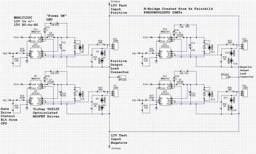
The Murata NMC1215SC DC/DC converters in a CPU-controlled H-Bridge design are experiencing repeated failures, with no obvious signs of the cause. The Murata NMC1215SC is a step-down DC-DC converter renowned for its efficiency and compact design, making it suitable for...
First circuit is for connecting VGA card to video projector or a monitor which accept VGA card frequencies and has RGB + Composite sync input. This circuit has been successfully used with Electrohome Projection Systems ECP 4100 data and...
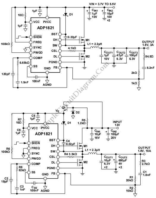
The schematic diagram below illustrates an ADP1821 Step Down DC-to-DC Converter circuit. This circuit employs the ADP1821, which is capable of regulating an output with a load exceeding 20 A, contingent upon the careful selection of power components such...
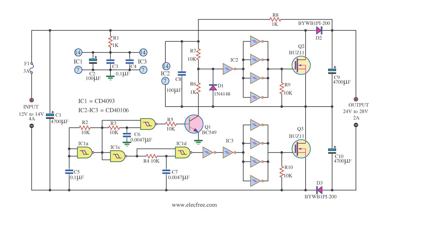
This is a DC to DC converter circuit designed to take an input of 12V to 24V at 4A and convert it to an output of 24V to 48V at 2A. The circuit utilizes simple components, including a CMOS...
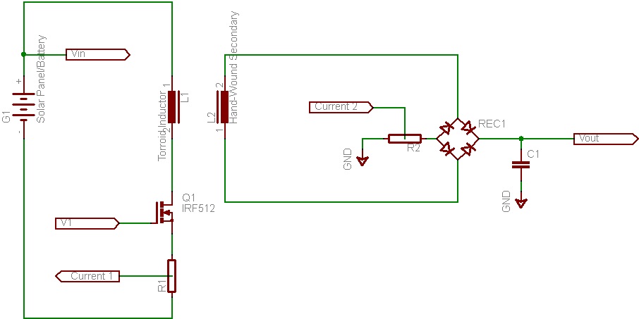
This document discusses the future direction of the Free Charge Controller project and proposes a new solar charge controller circuit. The Free Charge Controller project aims to enhance the efficiency and effectiveness of solar energy management systems. The proposed solar...
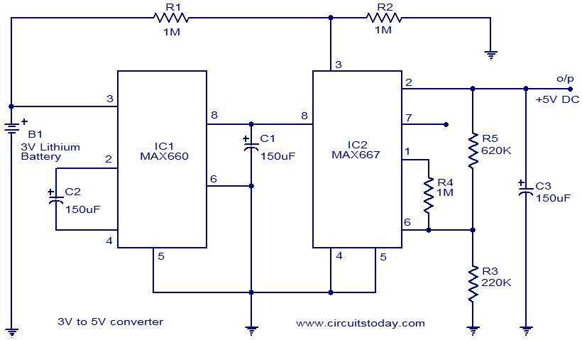
Voltage converter circuit diagram for converting 3 volts to 5 volts using CMOS monolithic ICs MAX660 and MAX667, which functions as a positive voltage regulator. The voltage converter circuit utilizes the MAX660 and MAX667 integrated circuits to step up a...