
-15 V 1-A Regulated Power Supply

The described circuit features a voltage regulation system utilizing a Darlington pair configuration with a TIP105 transistor. The circuit is designed to manage a -20 V supply voltage derived from a rectifier and filter stage, ensuring stable output voltage regulation under varying load conditions.
The TIP105 serves as the main pass transistor, which is a PNP type, and is responsible for controlling the output voltage. The base drive for the TIP105 is provided through resistor R5, which limits the base current and ensures proper operation of the transistor. The base voltage is influenced by a 6.2 V zener diode connected to the emitter of the uA723, a precision voltage regulator. The zener diode's anode is connected to pin 9, ensuring that the base of the TIP105 is adequately biased to maintain the desired output voltage.
The circuit also incorporates a feedback mechanism to enhance stability and response. Positive feedback is achieved through the interaction of resistors R1 and R2, which are strategically placed to sense current flow during short-circuit conditions. When the load exceeds a certain threshold, the increased current through R1 and R2 generates a voltage that forward biases the base-emitter junction of the TIP105. This action effectively increases the transistor's conduction, allowing more current to pass through and thereby stabilizing the output voltage against sudden load changes.
Overall, this circuit design is suitable for applications requiring robust voltage regulation with the ability to handle transient conditions while providing essential protection through feedback mechanisms. The careful selection of components and their configuration ensures reliable performance in various electronic applications.The supply receives -20 V from the rectifier/filter which is fed to the collector of the Darlington pnp pass transistor, a TIP105. The base drive to the TIP105 is supplied through resistor R5. The base of the TIP is driven from Vz terminal at pin 9, which is the anode of a 6.2-V zener diode that connects to the emitter of the uA723 output control transistor.
The method of providing the positive feedback required for feedback action is shown. This technique introduces positive feedback by increased current flow through resistors R1 and R2 under short-circuit conditions. This forward biases the base-emitter jun 🔗 External reference
Related Circuits
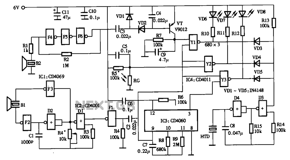
The timing circuit utilizes an electronic switch composed of F1, F2, and VT1 to reduce quiescent current to approximately 1 to 2 A with the 555 timer. Upon initial power-up, the voltage across capacitor C2 cannot instantly change, causing...
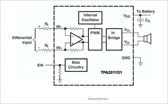
The TPA3007D1 is a 6.5-W mono bridge-tied load (BTL) class-D audio power amplifier featuring high efficiency, which eliminates the need for heat sinks. This amplifier can drive 8-ohm speakers with only a ferrite bead filter required to reduce electromagnetic...
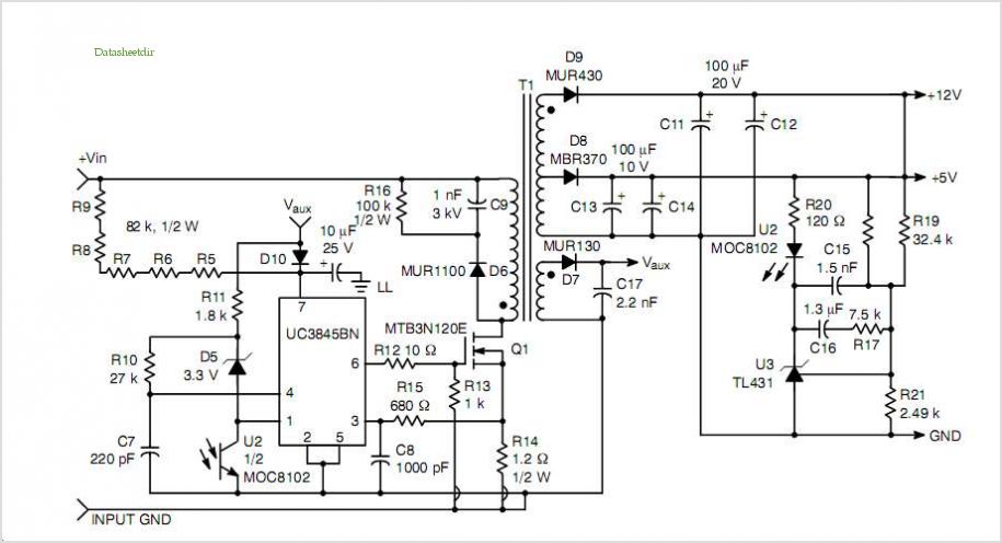
This post summarizes the work of experts in switching power supply schematic diagrams who are thoroughly knowledgeable about all aspects of the subject. Switching power supplies are crucial components in modern electronic devices, providing efficient voltage regulation and power conversion....
Initially, voltage from AC 220V or 110V enters the transformer, which reduces it to 12V AC. This AC voltage is then rectified using either four diodes or a bridge rectifier to convert it to DC voltage. The resulting DC...
In the absence of radiation, no current is drawn. At normal background radiation levels, the power consumption is extremely low. The instrument may be left on for several months without changing batteries. In this way, the detector is always...
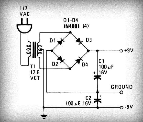
This is a power supply circuit that produces a voltage range of 12 to 24 V. It is straightforward, requiring only a bridge rectifier, a filter capacitor, and a transformer, without the need for a regulator. A bridge rectifier...