
15dB UHF TV Antenna Amplifier

The UHF band TV antenna preamplifier circuit is designed to enhance signal reception for television broadcasts in the UHF frequency range. The circuit operates with a gain of approximately 15 dB, which significantly improves the quality of the received signal. The core component of this design is the BF180 transistor, which is a high-frequency transistor suitable for UHF applications.
The circuit is divided into two main stages. The first stage consists of a band-pass filter, which is essential for selecting the desired frequency range while rejecting unwanted frequencies. This filter is constructed using capacitors (C1, CV1, C3, C7) and inductors (L1, L4). The choice of components is critical; for instance, the inductors L1 through L4 should be constructed as air-core coils to achieve a high Q-factor, which enhances the filter's performance by providing a sharper frequency response and reducing losses.
The second stage of the circuit functions as a base-common voltage amplifier. This configuration is characterized by its low input impedance, which is beneficial for matching the impedance of the antenna system. This matching is crucial for maximizing power transfer and minimizing signal reflection, ensuring that the maximum amount of signal is processed by the amplifier.
To minimize noise and interference, the assembled circuit should be enclosed in a metallic box. This enclosure serves multiple purposes: it shields the circuit from electromagnetic interference (EMI) and radio frequency interference (RFI), and it also provides a stable ground reference. It is important to connect the ground of the circuit to the metallic box to further reduce noise effects, enhancing the overall performance of the preamplifier.
In summary, this UHF band TV antenna preamplifier circuit is a straightforward yet effective design, leveraging the properties of the BF180 transistor and careful component selection to achieve a significant gain, while the enclosure ensures reliable operation in various environments.This is an UHF band TV antenna preamplifier circuit With 15dB gain to build easily. It is formed based on BF180 UHF Transistor. The first stage is an band pass filter constructed by the C1, CV1, L1, L4, C7 and C3, the second stage is a base-common voltage amplifier with low input impedance to match. Build the L1 ~ L4 as air core coil to obtain high Q-Factor. After assembling, pack it into a proper metallic box and connect the ground of the circuit to the box to reduce noise effect. 🔗 External reference
Related Circuits
A very useful audio amp in an 8-pin DIL package. The IC features a very low minimum working supply voltage of 3V, low quiescent current, good ripple rejection, no crossover distortion and low power dissipation. More: Maximum supply voltages...
This simple amplifier can be used for many things. Together with Equalization and (small) speakers good for the computer instance. The circuit uses IC TDA 2003 amplifier. This IC is in a TO-220 housing, and has 5 pins. Decoupling...

The preamplifier circuit is designed to offer appropriate loading for phono cartridges with reluctance. It achieves a gain of approximately 25 dB at 1 kHz (converting an input of 2.2 mV to an output of 100 mV). The circuit...
The 30-watt amplifier circuit provides a suitable power boost from an input of 4 watts up to 6 watts. It is designed to operate within the 88-108 MHz FM broadcast band and maintains stability while delivering a clean output...
In recent years, following CD's introduction, vinyl recordings have almost disappeared. Nevertheless, a phono preamplifier is still useful for listening to old vinyl discs from a well-preserved collection. This simple but efficient circuit devised for cheap moving-magnet cartridges can...
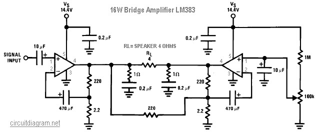
The following diagram illustrates a 16W bridge audio amplifier circuit. The design incorporates two LM383 power ICs in a head connection, making this amplifier a head amplifier. The LM383 is an older model that has been discontinued, which may...