
1Mhz-pierce-oscillators
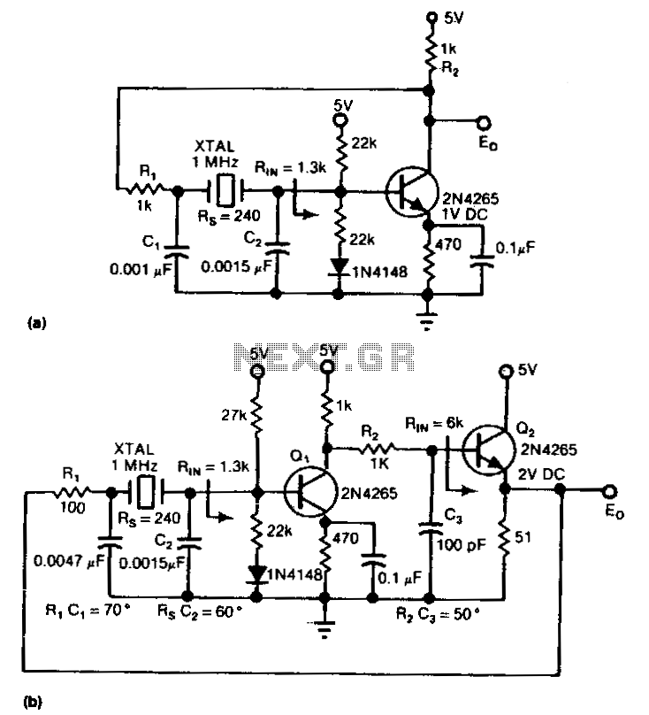
The circuit is an inverter configured as a linear amplifier. By incorporating a crystal and capacitors into the feedback path, the amplifier is transformed into an oscillator, enabling it to oscillate at or near the crystal's resonant frequency. Trimmer capacitor C2 is used to fine-tune the actual operating frequency of the circuit. The crystal utilized should be of the parallel-resonant type; the maximum frequency achieved will be influenced by the supply voltage, but it should be capable of reaching at least 1 MHz.
The described circuit employs an inverter as a linear amplifier, which is a common approach in oscillator design. The inverter, typically a CMOS or TTL device, provides the necessary gain to achieve oscillation. When the crystal is added to the feedback loop, it imposes a specific frequency characteristic on the circuit, allowing it to stabilize and oscillate at its resonant frequency. The feedback path is crucial as it determines the phase shift and gain required for sustained oscillation.
The parallel-resonant crystal serves as a frequency-selective element, ensuring that the circuit oscillates at a precise frequency determined by the crystal's specifications. The use of a trimmer capacitor (C2) allows for fine adjustments to the operating frequency, accommodating variations in component tolerances and environmental factors, thus ensuring optimal performance.
The maximum oscillation frequency, which can reach up to 1 MHz, is contingent upon the supply voltage and the characteristics of the crystal. Higher supply voltages may allow for higher frequencies, although the specific limits will depend on the inverter's specifications and the crystal's design. Careful selection of components and layout design will contribute to minimizing parasitic capacitance and inductance, which can affect the stability and performance of the oscillator circuit.
Overall, this circuit design is effective for applications requiring precise frequency generation, such as clock signals in digital circuits or RF applications, where stability and accuracy are paramount.The circuit is an inverter set up as a linear amplifier. Adding the· crystal and capacitors to the feedback path, we turn the amplifier into an oscillator and force it to oscillate at, or least very near, the crystal"s resonant frequency. Trimmer capacitor C2 adjusts the actual operating frequency of the circuit. The crystal should be a parallel-resonant type; maximum frequency will depend partly on supply voltage, but it should be possible to go to at least 1 MHz. 🔗 External reference
Warning: include(partials/cookie-banner.php): Failed to open stream: Permission denied in /var/www/html/nextgr/view-circuit.php on line 713
Warning: include(): Failed opening 'partials/cookie-banner.php' for inclusion (include_path='.:/usr/share/php') in /var/www/html/nextgr/view-circuit.php on line 713