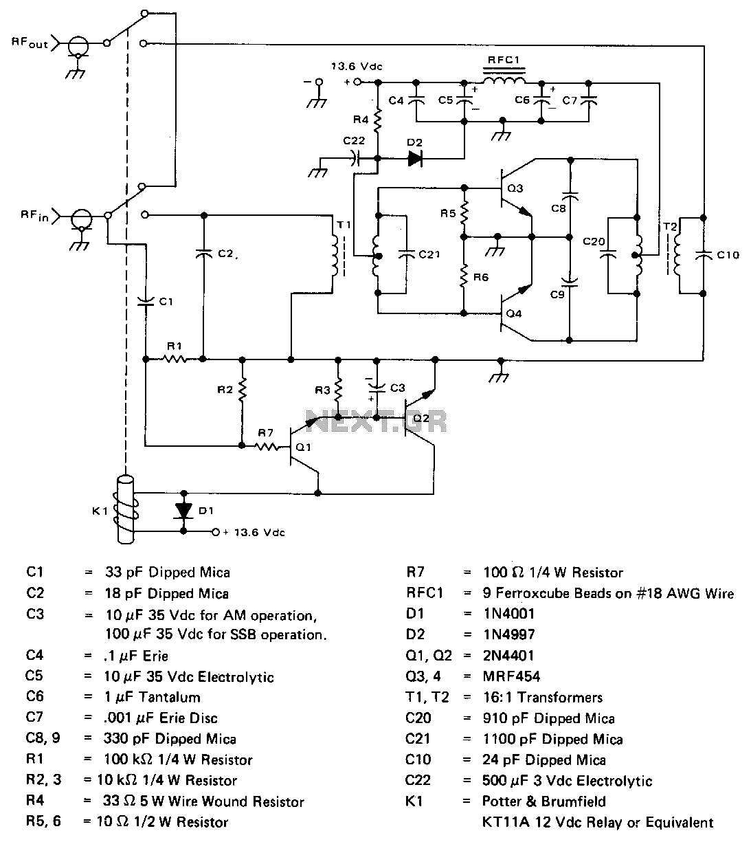
2-30Mhz-140w-linear-amplifier

The amplifier operates across the 2-30 MHz band with a relatively flat gain response and reaches gain saturation at approximately 210 W of output power. Both input and output transformers have a 4:1 turns ratio (16:1 impedance ratio) to achieve low input SWR across the specified band and a high saturation capability. It is important to interconnect the ground plane on the bottom of the board to the top, especially at the emitters of the MRF454s.
The described amplifier is designed for operation within the 2-30 MHz frequency range, providing a consistent gain profile across this spectrum. The gain saturation point is reached at an output power level of approximately 210 watts, making it suitable for high-power applications. The use of transformers with a 4:1 turns ratio translates to a 16:1 impedance ratio, which is crucial for maintaining a low standing wave ratio (SWR) at the input. This characteristic is essential for efficient power transfer and minimizing reflections that can degrade performance.
For optimal performance, careful attention must be paid to the grounding scheme of the circuit board. The recommendation to interconnect the ground plane on the bottom of the board to the top is particularly critical at the emitters of the MRF454 transistors. This practice helps to ensure that the ground potential remains stable and minimizes the risk of ground loops, which can introduce noise and affect the linearity and overall performance of the amplifier.
In summary, this amplifier design incorporates key features such as a flat gain response, high output power capability, and effective transformer coupling to achieve low input SWR. Proper grounding techniques are essential for maximizing performance and reliability, particularly in high-frequency applications.The amplifier operates across the 2 -30 MHz band with relatively flat gaio response and reaches gain saturation at approximately 210 W of output power. Both input and output transformers are 4:1 turns ratio (16:1 impedance ratio) to achieve low input SWRacross the specified band and a high saturation capability.
When using this design, it is important to interconnect the ground plane on the bottom of the board to the top, especially at the emitters of the MRF454s.