
2 Watt Audio Amplifier

The described 2 Watt audio amplifier circuit employs discrete components and operates in Class AB mode, which is characterized by its efficiency and sound quality. The use of complementary transistors, specifically the BD139 and BD140, allows for improved linearity and reduced crossover distortion, which is critical for high-fidelity audio applications.
In this configuration, the circuit typically begins with a differential amplifier stage, which can be realized using a pair of matched transistors. This stage amplifies the audio signal while maintaining a low noise floor. Following the differential stage, additional transistor stages are employed to further boost the signal level before it reaches the output stage.
The output stage, consisting of the BD139 and BD140, is responsible for delivering the final amplified audio signal to the speaker. The quiescent current, which is essential for preventing crossover distortion, is controlled by the adjustable 470-ohm preset resistor (PR1). This resistor allows for fine-tuning of the biasing conditions of the output transistors. Proper adjustment of PR1 is crucial, as it balances the trade-off between maintaining low distortion and minimizing power dissipation in the transistors.
The amplifier is designed to operate with a power supply voltage ranging from 12 to 18 Volts DC. This flexibility allows for compatibility with various power sources, making it suitable for a range of applications, from portable battery-operated devices to fixed installations. The capability to drive an 8-ohm speaker to output levels of around 5 watts, albeit with slightly higher distortion, indicates that the amplifier can be effectively used in small audio systems or as part of a larger audio setup.
Overall, this audio amplifier circuit represents a robust and versatile solution for audio amplification needs, exhibiting good performance characteristics for its time, with a focus on simplicity and ease of construction.A 2 Watt audio amplifier made from discrete components. This was one of the earliest circuits that I ever designed and built, in Spring 1982. At that time I had only an analogue meter and a calculator to work with. Although not perfect, this amplifier does have a wide frequency response, low harmonic distortion about 1.5%, and is capable of driving an 8 ohm speaker to output levels of around 5 watts with slightly higher distortion. Any power supply in the range 12 to 18 Volts DC may be used. The amplifier operates in Class AB mode; the single 470R preset resistor, PR1 controls the quiescent current flowing through the BD139/140 complimentary output transistors. Adjustment here, is a trade-off between low distortion and low quiescent current. 🔗 External reference
Related Circuits
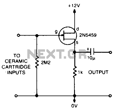
This circuit matches the very high impedance of ceramic cartridges, providing unity gain and low impedance output. By "loading" the cartridge with a 2.2MΩ input resistance, the cartridge characteristics are adjusted to closely compensate for the RIAA recording curve....
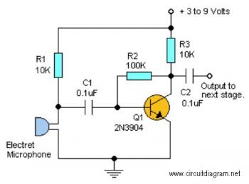
This straightforward circuit offers substantial amplification for weak audio signals, such as those from an electret microphone. It can be utilized in conjunction with an RF oscillator to create a highly sensitive RF transmitter. The audio microphone preamplifier circuit...
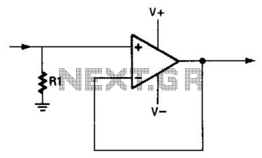
An operational amplifier (op amp) can function as a unity gain amplifier by connecting its output to its inverting input as illustrated. The load resistance (Rl) should be sufficiently low to prevent the op amp's bias current from introducing...
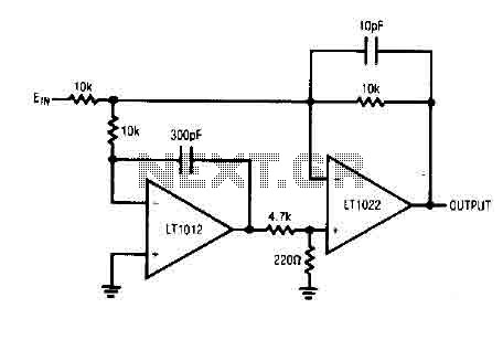
The circuit comprises a low drift LT1012 device and a high-speed amplifier LT1022. It functions as a unity gain inverter, with the summing node located at the junction of three 10k ohm resistors. The circuit monitors the summing node...
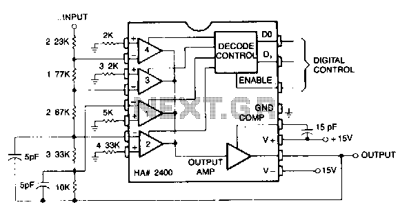
This circuit can be programmed for a gain of 0, -1, -2, -4, or -8. This could also be accomplished with one input resistor and one feedback resistor per channel in the conventional manner, but this would require eight...
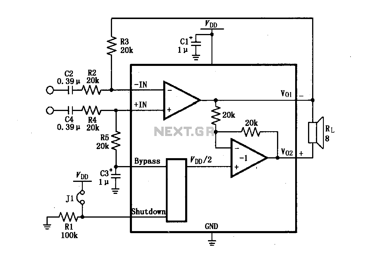
The LM4904 audio input differential amplifier circuit is presented. The audio signal is provided as a differential input to the +IN and -IN terminals. The LM4904 is a low-power audio input differential amplifier designed for high-performance audio applications. This circuit...