
250W Inverter Circuit

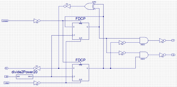
The circuit utilizes a 555 timer integrated circuit configured in astable mode to produce a square wave output at a frequency of 120 Hz. The frequency is determined by the resistor and capacitor values connected to the timer. This output signal is then directed to a CD4013BE dual D-type flip-flop, specifically using one of its flip-flops (IC1-a). The flip-flop operates as a frequency divider, effectively halving the input frequency, thus generating a 60 Hz clock signal.
The generated 60 Hz clock signal is crucial for controlling an array of Field Effect Transistors (FETs) labeled Q1 through Q6. These FETs can be used in various applications, such as switching or amplifying signals, depending on the circuit's design. The FET array is likely configured to respond to the clock signal, enabling synchronized operation of the connected loads.
In addition to these components, the circuit includes a transformer (T1) that steps down the voltage from a higher AC voltage source to a lower voltage level suitable for the circuit's operation. The transformer is specified as a center-tapped 12-/24-V transformer designed to operate at a 60 Hz frequency. The center-tap configuration allows for the generation of two different voltage levels, which can be beneficial for powering different parts of the circuit or for providing a reference ground.
This circuit design highlights the integration of timing, frequency division, and power management, making it suitable for applications that require precise timing control and efficient switching capabilities. Proper selection of component values and ratings is essential to ensure reliable performance and to meet the specific requirements of the intended application. A 555 timer (IC1) generates a 120-Hz signal that is fed to a CD4013BE flip-flop (ICl-a), which divides the input frequency by two to generate a 60-Hz clocking frequency for the FET array (Ql through Q6). Transformer Tl is a 12-/24-V center-tapped 60-Hz transformer of suitable size.
Related Circuits
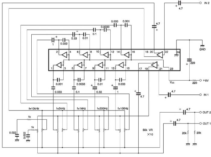
The BA3822 is a five-point stereo graphic equalizer integrated circuit that operates with two channels. Each channel can independently set five center frequencies using external capacitors. This integrated circuit supports a wide operating power supply voltage range (VCC =...

A simple doorbell circuit diagram and schematic designed using the UM66 IC, which is a music sound generator. This is an easy-to-make electronic doorbell circuit. The doorbell circuit utilizes the UM66 integrated circuit, known for its capability to generate musical...
Create a new project by selecting the New Project option from the Getting Started menu or by selecting File > New Project. This opens a dialog box where the desired project name and location can be entered. Choose a...
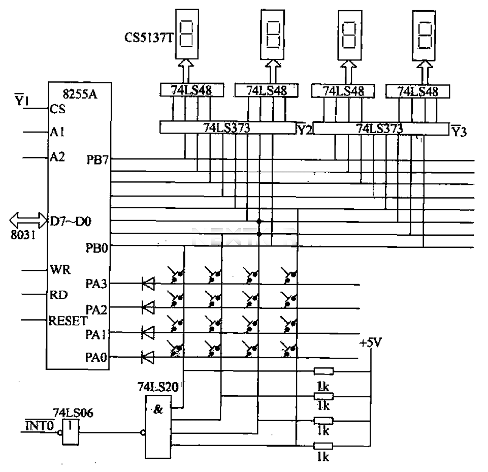
A 4x4 matrix keyboard system is designed for parameter settings, featuring numeric keys from 0 to 9 and function keys labeled A to F. The primary functions of the keyboard include completing parameter settings, selecting display modes, starting automatic...
This circuit is designed to demonstrate high frequency and high voltage, capable of producing up to approximately 30 kV, depending on the transformer utilized. It is an economical and straightforward project, primarily using a standard TV flyback transformer. The...
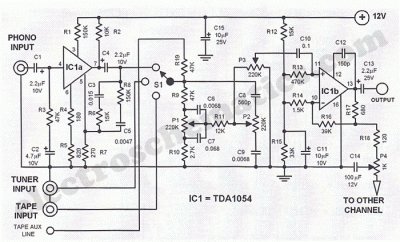
This Hi-Fi stereo preamplifier circuit is constructed using the TDA1054 integrated circuit (IC) from SGS. The TDA1054 is housed in a 16-pin DIL package and incorporates two separate preamplifier circuits. It is characterized by low noise and minimal issues...