
25W HiFi Audio Amplifier with MOSFET

The high-fidelity audio amplifier circuit is designed to deliver superior sound quality without the need for an additional pre-amplifier stage. This simplicity in design allows for a more direct signal path, which can contribute to enhanced audio performance.
The circuit utilizes a combination of resistors to set the gain and manage the input and output levels effectively. The resistors specified in the component list include:
- R1 and R4, each rated at 47K ohms and 1/4 watt, which are likely used in the feedback loop to stabilize the amplifier's gain.
- R2, with a resistance of 4.7K ohms, serves to set the input impedance, ensuring compatibility with a variety of audio sources.
- R3, a 1.5K ohm resistor, may be used to control the biasing of the amplifier stage, optimizing the operation of the active devices within the circuit.
- R5 and R6, rated at 390 ohms and 470 ohms respectively, are used to manage current flow and protect the circuit from excessive power dissipation.
The choice of 1/4 watt resistors indicates that this circuit is designed for moderate power applications, suitable for driving small to medium loads without significant thermal concerns. The overall design emphasizes high fidelity, making it ideal for audiophiles seeking to reproduce sound with minimal distortion.
In summary, this audio amplifier circuit is a straightforward yet effective solution for achieving high-quality sound reproduction, utilizing a carefully selected array of resistors to optimize performance and reliability.This is high fidelity, high quality audio amplifier circuit diagram. You dont need pre amplifier. Component list: R1,R4 = 47K 1/4W Resistors R2 = 4K7 1/4W Resistors R3 = 1K5 1/4W Resistors R5 = 390R 1/4W Resistors R6 = 470R 1/4W Resistors R.. 🔗 External reference
Related Circuits
The NE5539 wideband operational amplifier can be readily utilized as a color video amplifier. The gain remains stable, varying less than 0.5% from the minimum to the maximum of the specified range. The maximum differential phase shift is around...
The LMC568 is an amplitude-linear phase-locked loop that includes a linear voltage-controlled oscillator (VCO), fully balanced phase detectors, and a carrier detect output. It utilizes LMCMOS technology to achieve high performance while maintaining low power consumption. The VCO features...
The TS2418 is a monolithic integrated circuit telephone tone ringer that utilizes a bridge diode. When paired with an appropriate transducer, it serves as a replacement for traditional electromechanical bells. This device is compatible with either a piezo transducer...
This is the FET amplifier circuit, which utilizes an FET transistor. The gate of the FET must be negative relative to the source to achieve proper biasing. The voltage across the source resistor is generated by the drain current...
To complement the 60 Watt MOSFET Audio Amplifier, a high-quality preamplifier design was necessary. A discrete component topology, utilizing ±24V supply rails, was chosen, maintaining a minimal transistor count while still achieving low noise, very low distortion, and a...
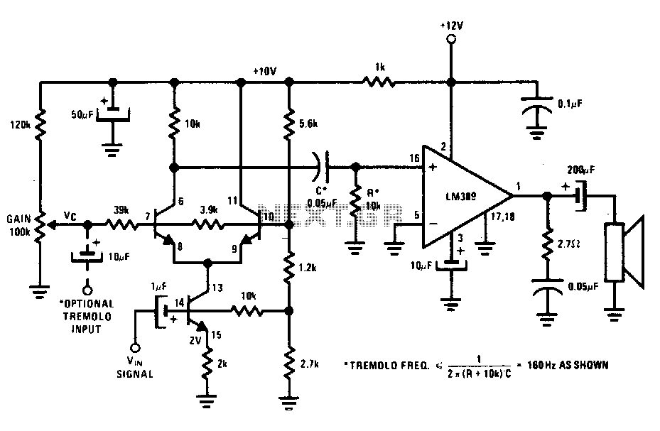
The transistors create a differential pair with an active current-source tail. This configuration, referred to as a variable-transconductance multiplier, produces an output that is proportional to the product of the two input signals. The multiplication effect arises from the...