
2x10 LED VU Stereo Meter

This project involves a circuit designed to visually represent audio volume levels through the illumination of LEDs in synchronization with music. The circuit is intended to connect directly to the speaker output of an audio amplifier, allowing it to sense the audio signal.
The core component of the circuit is a variable resistor (VR) rated at 10k ohms, which serves to adjust the input signal level. This variable resistor allows for fine-tuning of the sensitivity of the circuit to accommodate different audio sources and amplification levels.
To enhance the visual display, multiple LEDs can be utilized. The choice of LED colors is flexible, enabling customization to achieve an aesthetically pleasing effect. For larger installations, such as a wall-mounted display, an optional output transistor can be incorporated. This transistor will facilitate the driving of multiple LEDs simultaneously, ensuring that the brightness and responsiveness of the display are maintained even with a larger number of LEDs.
The project includes two identical units to represent both the left and right audio channels, allowing for a complete stereo audio visualization. Each unit can operate independently, ensuring that the volume levels of each channel are accurately represented through their corresponding LED displays.
In summary, this circuit is a versatile and visually engaging way to represent audio volume levels, with options for customization and scalability to fit various applications.I like to see lights move to music. This project will indicate the volume level of the audio going to your speakers by lighting up LEDS. The LEDS can be any color so mix them up and really make it look good. The input of the circuit is connected to the speaker output of your audio amplifier. You want to build two identical units to indicate both right and left channels. The input signal level is adjusted by the 10k ohm VR. If you wish to make a very large scale model of this unit and hang it on your wall there is an optional output transistor that can drive many LEDS at once. The unit I built drove three LEDS for each ou 🔗 External reference
Related Circuits
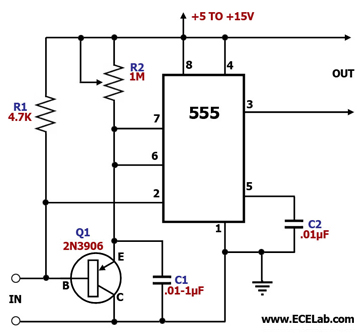
In this circuit, the 555 timer is utilized in an innovative manner as a voltage-controlled switch. The widely used NE555 can perform effectively in various applications. The 555 timer, a versatile integrated circuit, is commonly employed in timer, delay, pulse...
Flashing frequency can be varied by changing R1 value in the 1M - 4M7 range. This circuit is very efficient when driving a small 3.2V incandescent lamp. In this case omit the LED and R3, connecting the bulb across...
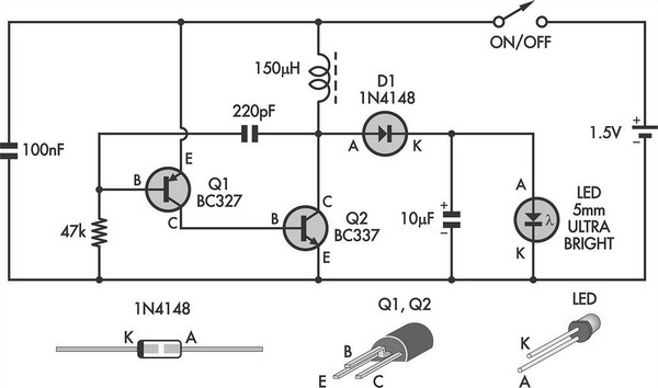
This simple LED torch is driven by a 2-transistor blocking oscillator that steps up the voltage from a 1.5V cell. It relies on the inherent current limiting of the 150 µH choke to protect the white LED from overdrive....
Function: Used to measure the voltage change minute by management before the temperature diodes. Component: IC, Diode, Resistor, 3-1/2 digit LCD (SP521PR). The circuit described functions as a voltage measurement system designed to monitor minute voltage changes, particularly in relation...
This project involves a simple and engaging light-activated LED circuit that illuminates an LED in response to light exposure. The circuit is straightforward to construct, requiring only six components. A photoresistor is utilized for light sensing, while a 2N2222...
The project is developed by Team Stark, with Gilbert as the leader and team members Martin and Janssen. The tasks have been divided into three parts. The first part includes camera control, login database, installer, and network setup, which...