
3 Input mic mixer circuit

The circuit design integrates four uA741 operational amplifiers, which are versatile and commonly used in audio applications due to their low noise and high gain characteristics. The three input microphones connect to the non-inverting terminals of the first three operational amplifiers (IC1, IC2, IC3). Each of these amplifiers is configured with resistors that set the gain to around 40 dB, ensuring that the weak microphone signals are adequately amplified for further processing.
The output of each preamplifier feeds into the inverting input of the fourth operational amplifier (IC4), which is configured as a summing amplifier. This configuration allows the mixer to combine the amplified signals from the three microphones into a single output signal. The summing amplifier also includes feedback and input resistors that determine its gain, which is set to approximately 5 dB in this design.
The overall gain of the circuit, calculated as the sum of the gains from the preamplifiers and the summing amplifier, results in a total gain of about 45 dB. This gain is suitable for driving subsequent audio processing stages or for direct connection to a power amplifier.
Power supply connections for the uA741 ICs are typically provided by dual supply voltages, commonly ±15V, which is necessary for proper operation of the op-amps in audio applications. Bypass capacitors may be included near the power supply pins of each IC to filter out any noise and ensure stable operation.
The circuit can be implemented on a printed circuit board (PCB) or a breadboard for prototyping. Proper grounding and layout considerations are essential to minimize noise and interference in audio applications. Overall, this microphone mixer circuit offers a straightforward solution for mixing multiple audio signals with minimal complexity while maintaining high-quality sound reproduction.Here is a simple 3 input mic mixer circuit using the popular uA 741 ICs. Four 741s are used here. IC1, IC2, IC3 are used as preamplifiers. They produce a gain of around 40 decibel to the individual input signals. The IC4 is wired as a summing amplifier to add the signals from three preamplifiers. IC4 also gives a gain of around 5decibel to the final output signal. Total gain of the system is around 45decibel. 🔗 External reference
Related Circuits
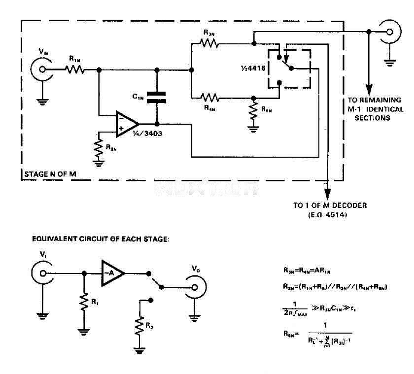
CMOS switches are utilized to select entries in audio circuits. While these switches can introduce unacceptable levels of distortion, incorporating them into the feedback network of an operational amplifier (op amp) can effectively minimize this distortion. The circuit employs...
This circuit illustrates a flip-flop timer circuit diagram utilizing the 4017 integrated circuit (IC). The key feature includes a push-button switch (S1) that discharges capacitor (C1) through resistor (R2). The 4017 decade counter IC is commonly used in timer and...
This solid-state push-pull single-ended Class A circuit is capable of providing sound quality comparable to that of valve amplifiers. It delivers an output power of 6.9W when measured across an 8 Ohm loudspeaker cabinet load, with reduced total harmonic...
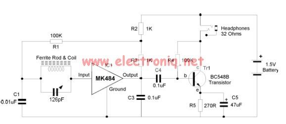
The MK484 AM radio circuit offers a comprehensive solution featuring an RF amplifier, detection, and an automatic gain control (AGC) circuit. It requires only a few external components to achieve high-quality AM tuning. The circuit has an input impedance...
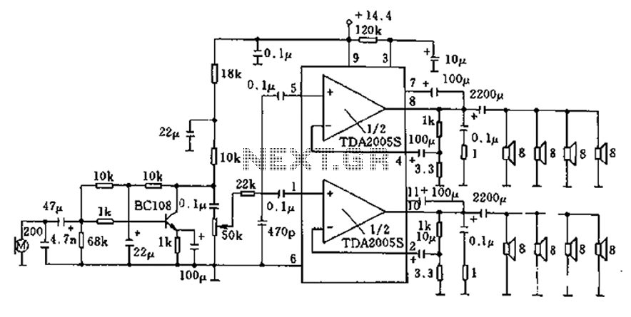
20W bus radio and megaphone circuit utilizing the TDA2005S double low-frequency power amplifier integrated circuit design. The front end can be connected to either a microphone input or a low-frequency radio output voltage amplification stage. Each TDA2005S provides 10W...

Digital Command Control (DCC) provides significant advantages over traditional DC analog control systems, primarily due to its simplified wiring. DCC enables the individual control of multiple locomotives on the layout without requiring electrical isolation of track sections. The main...