
3Input And Gate Comparator

The described circuit functions as a multi-input comparator, specifically designed to yield a high output signal when all three input signals are in a high state (logic level '1'). The operational amplifier (op-amp) configuration utilized here is critical for determining the output based on the relationships between the input currents.
In this setup, the non-inverting input of the op-amp receives signals from three distinct inputs. The inverting input is connected through a resistor, R4, which plays a vital role in setting a threshold for the current comparison. When all three inputs are high, the current flowing into the non-inverting input surpasses the current flowing into the inverting input, resulting in a high output signal.
The ability to convert this configuration into an AND gate is noteworthy. By transposing the connections of the two inputs of the op-amp, the circuit can be reconfigured to operate under the principles of a standard AND gate. In this new configuration, the output will only be high when all inputs are high, thus fulfilling the logical AND operation.
For practical implementation, the values of the resistors, particularly R4, must be chosen carefully to ensure that the circuit operates effectively within the desired voltage and current ranges. The op-amp should be selected based on its supply voltage and input voltage range to ensure reliable performance. Additionally, consideration should be given to the power supply design to maintain stability during operation.
This circuit can be utilized in various applications, including digital signal processing, control systems, and logic circuit design, where multiple conditions must be met to trigger an output response. The versatility of this circuit makes it a valuable component in complex electronic systems. This circuit has high output only when all three inputs are high. The noninverting-input current, when all thre e inputs are high, must exceed that of the inverting input, as determined by R4. The circuit can be converted to a AND gate by transposing the two inputs of the op amp.
Related Circuits
Digital electronics tutorial about the Logic NOT Gate, also known as an Inverter, and the Logic NOT Gate Truth Table used in TTL and CMOS Logic Gate circuits. The Logic NOT Gate, or Inverter, is a fundamental building block in...
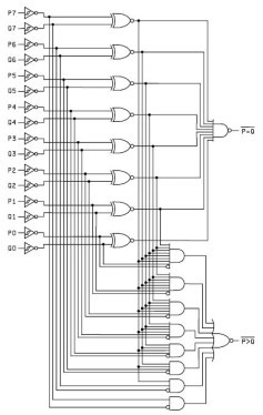
This Magnitude Comparator can be used to perform comparisons of two 8-bit binary or BCD words. The output provides both a P equals Q function and a P greater than Q function. A Magnitude Comparator is typically classified as...
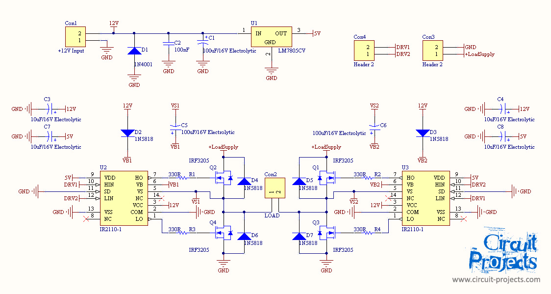
Assistance is required for a final year project involving the design of a grid-connected inverter. The focus is on developing a full bridge inverter circuit. The grid-connected inverter is a crucial component in renewable energy systems, particularly in solar photovoltaic...
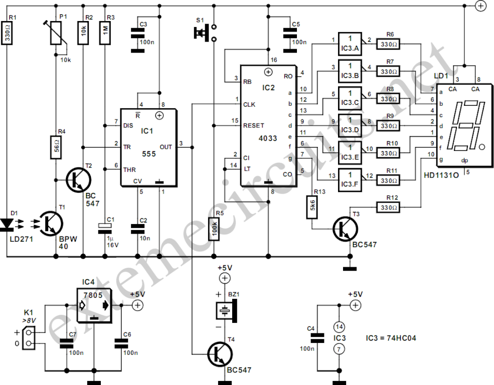
The circuit described here counts the number of times an infrared beam is interrupted. It can be utilized to count the number of individuals entering a room or to track how often an object, such as a ball, passes...
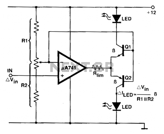
An operational amplifier (op amp) is utilized as a comparator and as a current sink for an LED. The output voltage of the amplifier varies by approximately 1.4 V based on the direction of the current. At any given...
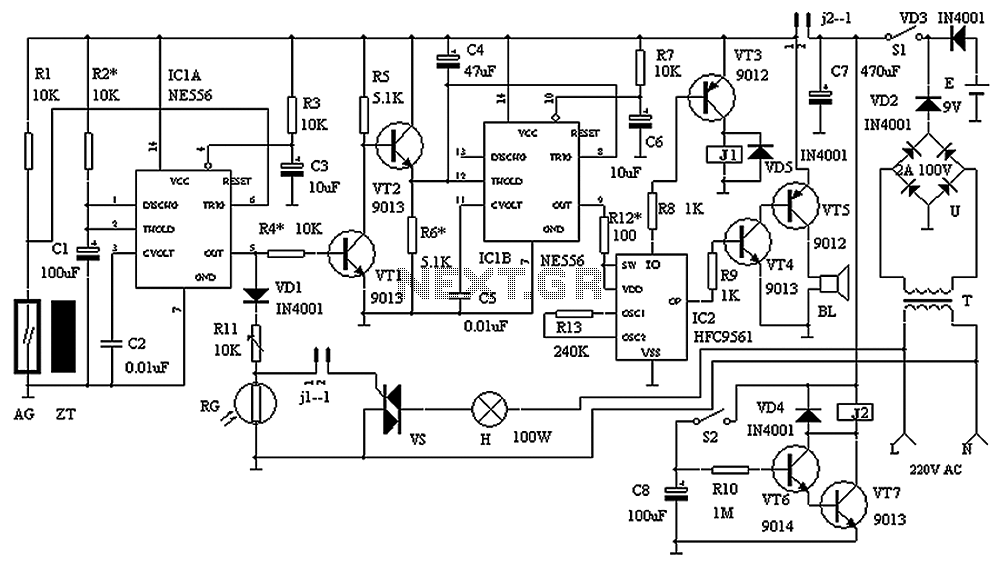
The circuit consists of a triggering device, a monostable delay circuit, an alarm sound generator, an audio amplifier circuit, and a light control circuit, with a partially blocking preset circuit and power circuit. When the door is locked and...