4-18Mhz-converter

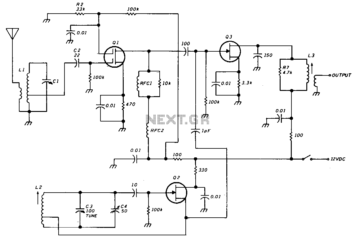
The unit consists of an RF amplifier Q1, a local oscillator Q2, and a mixer Q3. The two frequency bands are covered without a band switch by utilizing an intermediate frequency (IF) of 3.5 MHz. The oscillator operates within a range of 7.5 to 14.5 MHz. Incoming signals ranging from 4 to 11 MHz are mixed with the oscillator to generate a 3.5-MHz IF. Similarly, signals from 11 to 18 MHz are also mixed with the oscillator to produce the same 3.5 MHz IF. At any given oscillator frequency, the two incoming signals are separated by 7 MHz. The RF amplifier input, consisting of capacitor C1 and inductor L1, forms a high-Q, lightly loaded, tuned circuit, which is crucial for effective band separation.
The electronic schematic described encompasses a straightforward yet efficient architecture for signal processing within a specified frequency range. The RF amplifier Q1 is tasked with amplifying weak incoming radio frequency signals before they are fed into the local oscillator Q2. This oscillator generates a stable frequency that is mixed with the incoming RF signals in mixer Q3.
The design's choice of a 3.5 MHz intermediate frequency is significant, as it allows for effective filtering and amplification of the desired signals while minimizing interference from unwanted frequencies. The local oscillator's frequency range of 7.5 to 14.5 MHz ensures that signals within the specified input range are adequately processed. The mixing process in Q3 enables the combination of the incoming signals with the oscillator frequency, resulting in the generation of the intermediate frequency.
The separation of the two incoming signal bands, specifically the 4 to 11 MHz and 11 to 18 MHz ranges, is facilitated by the high-Q tuned circuit formed by capacitor C1 and inductor L1. This configuration enhances the selectivity of the RF amplifier, allowing it to effectively discriminate between closely spaced frequencies. The lightly loaded characteristic of the circuit further contributes to the overall performance by reducing losses and maintaining signal integrity.
In summary, the schematic effectively integrates an RF amplifier, local oscillator, and mixer to create a versatile and efficient system for processing a range of radio frequencies, leveraging high-Q tuning techniques for optimal band separation and signal clarity.The unit consists of rlamplifier Q1, local oscillatorQ2, and mixer Q3. The two bands are covered without a bandswitch by using an i-f or 3.5 MHz. The oscillator range is 7.5 to 14.5 MHz. Incoming signals from 4 to 11 MHz are mixed with the oscillator to produce the 3.5-MHz i-f. Signals from 11 to 18 MHz are mixed with the oscillator to also produce an i-f of 3.5 MHz. At any one oscillator frequency, the two incoming signals are 7 MHz apart. Rf amplifier input Cl/L1 comprises a high-Q, lightly loaded, tuned circuit; this is essential for good band separation.