
470 Mw complementary-symmetry audio amplifier

The described circuit is engineered to provide high fidelity audio performance, characterized by minimal distortion and a wide frequency response. The distortion level, being less than 2%, indicates that the circuit is capable of accurately reproducing audio signals without introducing significant artifacts, which is crucial for high-quality audio applications.
The frequency response range of 15 Hz to 130 kHz signifies that the circuit can effectively handle both low and high-frequency signals. The lower limit of 15 Hz ensures that deep bass sounds are reproduced accurately, while the upper limit of 130 kHz allows for the reproduction of high-frequency sounds that can enhance the overall audio experience, including the nuances in music and sound effects.
In practical applications, such a circuit can be utilized in various audio equipment, including amplifiers, mixers, and equalizers. The flat response within 3 dB across the specified frequency range suggests that the circuit does not favor any particular frequency, thereby ensuring a balanced output. This is particularly important in professional audio settings where accurate sound reproduction is essential for mixing and mastering audio tracks.
To achieve these performance metrics, the circuit may incorporate high-quality components such as precision resistors, capacitors, and operational amplifiers, along with careful layout design to minimize noise and interference. Additionally, feedback mechanisms may be employed to stabilize the gain and further reduce distortion. Overall, this circuit design is well-suited for audiophiles and professionals seeking high-performance audio solutions.This circuit has less than 2% distortion and i&flat within 3 dB from 15 Hz to 130 kHz.
Related Circuits
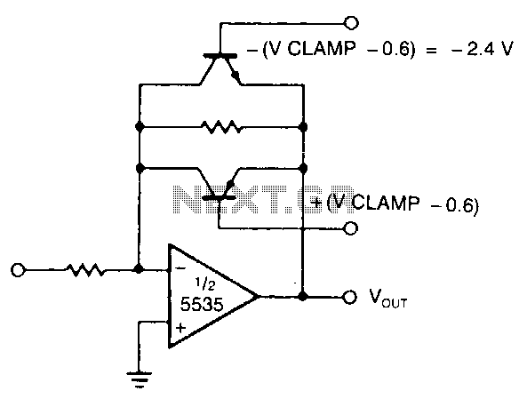
The modified inverting amplifier employs an active clamp to precisely limit the output swing. Consideration must be given to the VBE of the transistors. The output swing is restricted by the base-emitter breakdown of the transistors. A straightforward circuit...

This design circuit functions to filter out interference signals, ensuring that the signal received from a Morse code station is distinct. The circuit utilizes the earliest mode of radio communications, which employs Morse Code on a continuous wave carrier...
This Hi-Fi stereo preamplifier circuit is designed with the TDA1054 IC from SGS. The TDA1054 is a 16-pin DIL integration that includes two separate preamplifier circuits. It is a low-noise preamp with minimal issues during the construction process. The...
This circuit indicates the power level delivered to a loudspeaker. A dual-color LED displays green at approximately 1 watt, orange at 1.5 watts, and bright red at levels exceeding 3 watts. The circuit is connected in parallel with the...
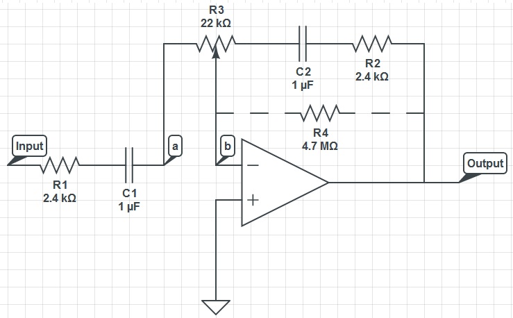
This circuit can function as a treble control circuit, with high-frequency gain occurring when resistor R3 is set to a value that makes points a and b equal (denoted as k=0). Conversely, high-frequency attenuation occurs when R3 is set...
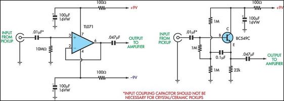
This achievement demonstrates the feasibility of creating a balanced dynamic microphone preamplifier, which is relatively straightforward. This preamplifier is particularly well-suited for microphones with an output impedance ranging from 200 ohms to 600 ohms. The advantages of this preamplifier...