
5 W ATV TRANSCEIVER

The transmitter operates within the 440 MHz band and is designed for amateur television (ATV) applications. The integration of both video and audio sections allows for simultaneous transmission, making it suitable for broadcasting purposes. The output power of five to six watts PEP is adequate for effective transmission over moderate distances, ensuring a clear signal for receiving stations.
The use of PIN diodes for channel switching provides rapid and reliable transitions between the three available channels, enhancing the versatility of the transmitter. These diodes are known for their low insertion loss and high switching speed, which is critical in maintaining signal integrity during channel changes.
The downconverter section of the schematic typically involves the mixing of a local oscillator signal with the incoming RF signal, allowing for the downconversion of the frequency to a more manageable level for further processing. This section is crucial for ensuring that the transmitted signals remain within the required frequency specifications while also facilitating the reception of incoming signals.
Overall, the described transmitter schematic is a robust design that effectively combines video and audio transmission capabilities, making it a valuable component for ATV enthusiasts and professionals in the field. The thoughtful integration of components and the strategic use of technology such as PIN diodes contribute to the efficiency and performance of the device.For the transmitter schematic (part of this transceiver), see entry entitled S-W ATV Transmit-ter for 440 MHz, Fig. 5-1. The downconverter portion is shown here.This transmitter contains both a video and sound section. Five to six watts PEP on synch tips of NTSC video are produced. Three channels are available. Channel switching is via PIN diodes. Power.. 🔗 External reference
Related Circuits
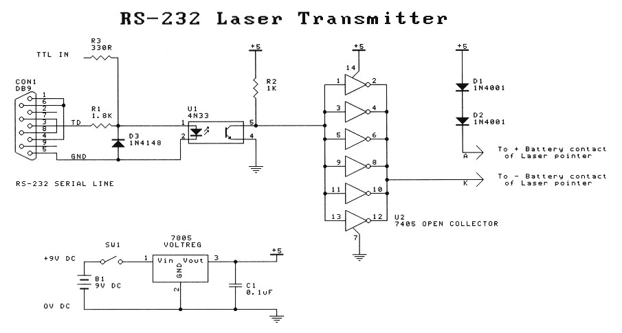
This project is intended for entry-level laser experimenters. The circuit enables communication between two computers with serial (RS-232) capabilities over a distance of 200 meters using a laser beam. A low-cost transmitter-only circuit is also provided for one-way communication...
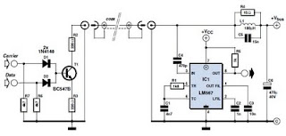
This circuit was designed to transmit commands over an LNB coaxial cable. An LNB (Low-Noise Block downconverter) is commonly used for satellite TV reception and is positioned at the focal point of a satellite dish. The circuit generates a...
In this circuit, the SP6126 is configured as a Zeta converter to supply 0.3A for driving four series-connected LEDs. The SP6126 is a flexible and economical controller that provides the necessary functions required by a Zeta regulator. This report...

The 7MHz CW transceiver is constructed using the MC3362P integrated circuit, originally intended for a 10MHz band transceiver. Due to concerns regarding unexpected neighboring spurious signals, the frequency was altered to 7MHz, leading to the completion of the transceiver....
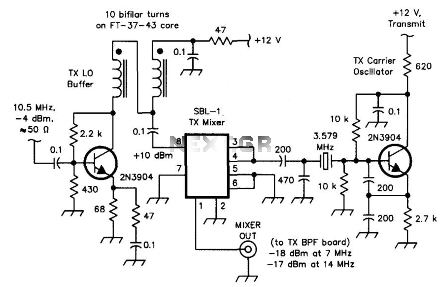
The transceiver mixer and carrier oscillator in the band-imaging (7- and 14-MHz) CW transceiver. Careful selection of drive levels and the use of a spectrally clean carrier oscillator ensure low spurious-signal content in the transmitter output. This transceiver mixer...
The original firmware is functional on amateur radio bands; however, it lacks user-friendliness. Wulf-Gerd, DL1FAC, has developed a new firmware that is significantly more suitable for amateur radio users. This firmware is open source, allowing for flexible frequency adjustments,...