
5000 Volts arc supply

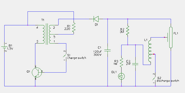
The described circuit operates as a manually triggered high-voltage spark generator, capable of producing peak output voltages exceeding 5,000 volts. The primary components include an audio transformer (T1) and a trigger coil (T2), which are critical for the voltage step-up and discharge process.
T1, the audio transformer, is responsible for stepping up the input voltage to approximately 500 volts at point X in the schematic. This transformer is typically compact and designed for low current applications, making it suitable for generating the necessary voltage levels without excessive power consumption. The high-voltage output from T1 is essential for initiating the spark generation process.
The second component, T2, serves as the trigger coil, which can either be a standard trigger coil commonly found in strobe kits or a custom-wound coil similar to those utilized in stun gun designs. The choice of T2 is crucial, as it determines the circuit's overall performance and reliability. A standard trigger coil may provide adequate performance for basic applications; however, a custom coil can be tailored to optimize the spark generation characteristics.
It is important to note that excessive arcing can lead to internal arcing within T2, resulting in permanent damage and short-circuiting the coil. To prevent this, it is advised to start with a small arc and gradually increase the distance until the maximum arc length is achieved. Once the maximum distance is found, it is prudent to reduce the arc length slightly to ensure a safety margin, thereby preventing potential damage to the components.
Overall, this circuit design emphasizes careful handling and gradual adjustments to achieve high voltage spark generation, while minimizing the risk of component failure. Proper understanding and implementation of the described components and operational guidelines will enable effective use of this high-voltage spark generator.A Very Low Current, High Voltage Spark, that is "Manually Triggered". Although its not easily Measured, the Peak Ouput voltage will be over 5,000 Volts. T1 is a small audio transformer and it steps up the voltage to about 500 Volts at Point "X" on the schematic. The main power limitation to this device is T2. It can be a Standard Trigger Coil, like those used on Strobe Kits, or a Custom made Trigger Coil. For A Custom coil, You can wind one Simular to those in my Stun Gun Write-ups. Which-Ever Coil you use for T2, If you try for Too long of an Arc, It will Arc Internally, Permanently Shorting itself Out.
So Start with a Small Arc and Slowly Increase it to try and find the Maximum Distance. Than Reduce it Slightly to give a small Safety Margin. 🔗 External reference
Related Circuits
This document provides a step-by-step guide for modifying a disposable camera flash unit to serve as a power supply for a Geiger tube. The process involves removing the flash tube and trigger transformer from the circuit board by gently...
An increasing number of appliances draw a very small current from the power supply. When designing a mains-powered device, one can typically choose between a linear power supply and a switch-mode power supply. However, if the total power consumption...
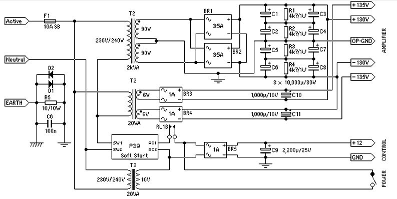
Power supply for a 1500-watt audio power amplifier. This power supply circuit is paired with a high-power audio amplifier rated at 1500 watts. A serious approach is required to design the power supply for the amplifier. First, a step-down...
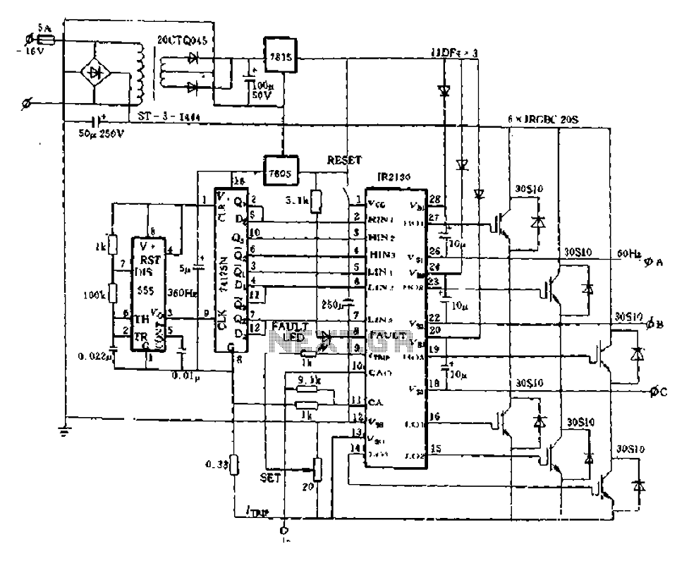
The application of the aforementioned advantages allows the IR2130 to be effectively utilized for DC cut crossing speed, DC servo systems, three-phase power inverters, and switching power supplies. Additionally, it is applicable in inverter power supplies, uninterruptible power supplies...
The telephone ring generator described generates the necessary aerial voltage using a simple switched-mode power supply (SMPS). It incorporates a CMOS Schmitt Trigger-based oscillator, a 10 mH inductor, a high-voltage switching transistor (such as the TIP47 or another high-voltage,...
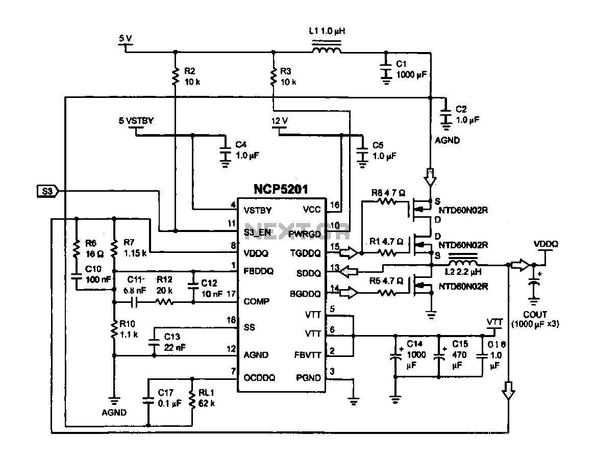
Computer memory power supply circuit (NCP5201). This circuit illustrates a typical power supply configuration for computer memory, utilizing the NCP5201 power management chip. It features a dual-output design. The NCP5201 is a highly integrated power management solution designed specifically for...