
555 tri-color flash circuit diagram ornaments

The circuit utilizes a dual 556 timer IC, which contains two independent timing circuits capable of functioning as astable multivibrators. The left section of the IC is configured to produce a higher frequency output of approximately 2 Hz. This is achieved through the combination of resistors R1 and R2, which determine the charge and discharge time of capacitor C1, thus setting the oscillation frequency. The output from this section can be connected to an LED to produce a blinking red light.
Conversely, the right section of the 556 operates at a lower frequency of around 0.5 Hz. Resistors R4 and R5, along with capacitor C2, are selected to set the timing characteristics for this multivibrator. The output from this section drives a green LED, creating a slower blinking effect compared to the left section.
The outputs from pins 5 and 9 of the 556 IC are connected to the anodes of the respective LEDs. When the left multivibrator output is high, the red LED illuminates, while the right multivibrator output drives the green LED. The alternating blinking of these LEDs results in a visual effect that transitions between red and green, and when both LEDs are illuminated simultaneously, it produces an orange hue.
The choice of component values for resistors and capacitors is crucial for achieving the desired blinking rates and ensuring that the LEDs operate within their specified current ratings. Proper heat dissipation considerations should also be made, especially if the circuit is powered for extended periods. Additionally, the circuit can be further enhanced by incorporating a power supply regulation component to maintain consistent voltage levels for reliable operation. As shown, the circuit consists of a dual-core 556 and the light emitting tube. The left half of the IC (556 1/2) composition R1, R2, C1, etc. frequency of about 2Hz multivibrat or; the right half of the IC (556 1/2) composition and R4, R5, C2 and so on about 0.5 the multivibrator Hz. The output of 5,9 feet respectively drive the red, green light-emitting diode, resulting in red, orange, green three colors that blink of glory.
Related Circuits
A high-quality tone burst generator can be constructed using a 556 Dual Timer. The first half of the timer can be configured as a one-shot, while the second half can function as an oscillator. The 556 Dual Timer is an...
This is a simple game circuit designed for multiplayer enjoyment. The objective is to score one hundred points within a limited timeframe. To restart the game, the S1 button switch must be pressed. It is important to ensure that...
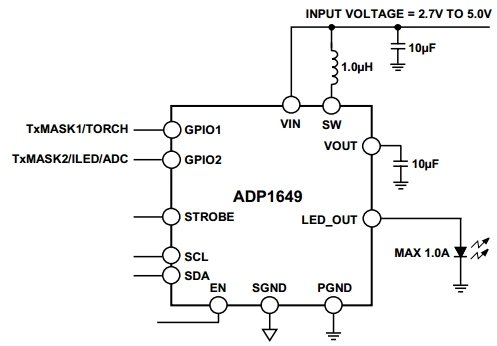
The ADP1649 is a compact and highly efficient single white LED flash driver designed for high-resolution camera phones, enhancing the quality of pictures and videos. The ADP1649 integrates advanced features that optimize the performance of single white LED flash applications....
Although the integrated circuit (IC) has largely replaced this circuit, the flexibility of the discrete device design still makes it practical. The components are readily available and cannot easily be eliminated. If desired, a small piece of metal can...
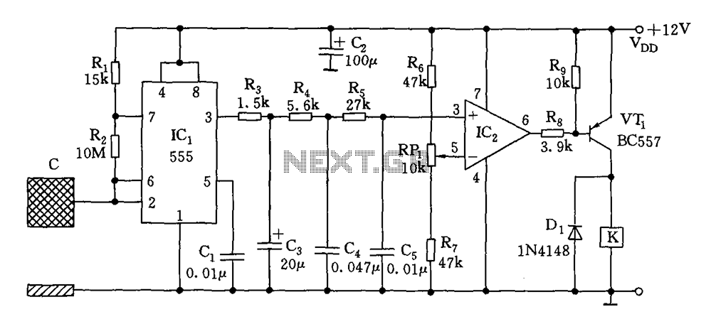
The switch circuit consists of a capacitive oscillator, an integration network, and a comparator circuit that controls a relay. When a body comes close to the induction plate, the inductive capacitance to ground increases, causing the 555 astable multivibrator...
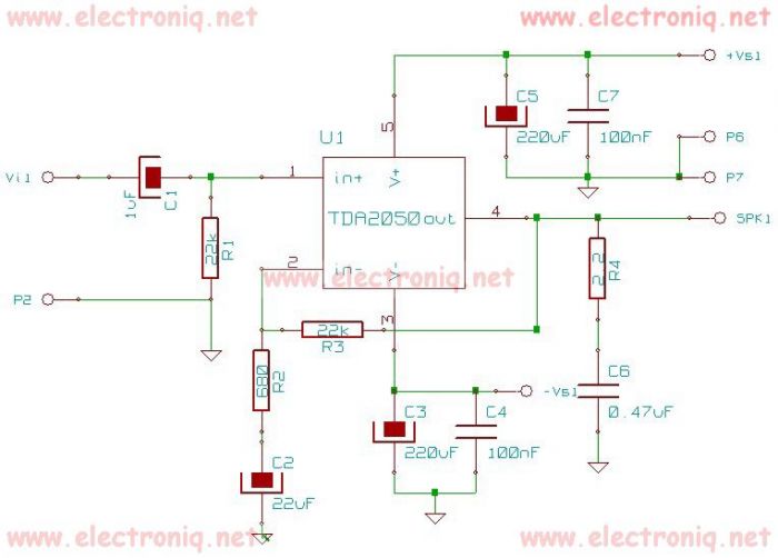
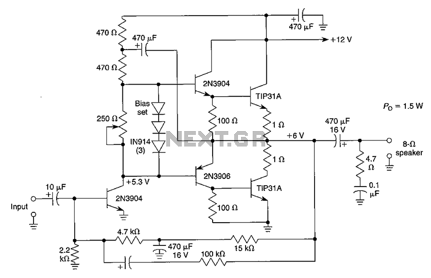
The TDA2050 integrated circuit can be used to design a simple high-fidelity audio power amplifier, intended for use as a Class AB audio amplifier. Due to its high power capabilities, the TDA2050 audio power amplifier can deliver up to...