
5V 0.5A power supply

The circuit operates as a linear voltage regulator, leveraging the ZN424E integrated circuit to provide a stable output voltage. The feedback components, R2 and R3, play a crucial role in ensuring that the output voltage remains constant despite variations in load conditions or input voltage fluctuations. This feedback mechanism adjusts the base voltage of the output transistor Tr2, which acts as a pass element, allowing for efficient regulation of the output voltage.
Transistor Tr1, in conjunction with resistor R5, forms the initial stage of voltage regulation. The configuration ensures that the ZN424E maintains its required output voltage by adjusting the current flowing through Tr2 based on the feedback received from the output voltage. The load connected to the collector of Tr2 experiences a regulated voltage, which is critical for applications requiring precise voltage levels.
The performance metrics indicate that the circuit is highly stable, with minimal output noise and ripple, making it suitable for sensitive electronic applications. The load regulation of 0% signifies that the output voltage remains unaffected by changes in load current, which is an essential feature for maintaining consistent performance. The temperature coefficient of ±100 ppm/°C indicates that the output voltage will only vary slightly with temperature changes, enhancing the reliability of the circuit in varying environmental conditions. The current limit of 0.5 A ensures that the circuit can safely handle loads without risk of damage or failure. Overall, this circuit design exemplifies effective voltage regulation through careful component selection and configuration.The circuit is essentially a constant source modified by the feedback components R2 and R3 to give a constant voltage output. The output of the ZN424E need only be 2 volts above the negative rail, by placing the load in the collector of the output transistor Tr2.
The current circuit is achieved by Trl and R5 This simple circuit has the following performance characteristics: Output noise and ripple (full load) = 1 mV rms. Load regulation (0 to 0 A) = 0%. Temperature coefficient — ± 100 ppm/°C. Current limit = 05 A.
Related Circuits
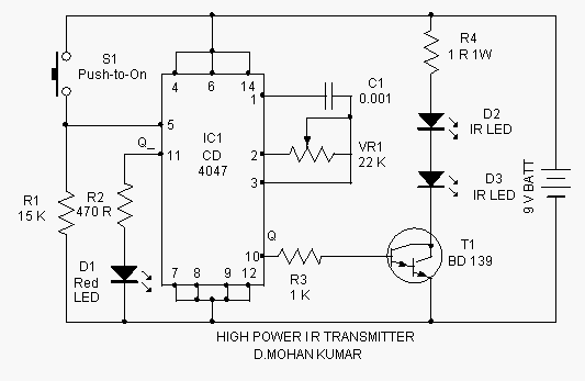
This infrared transmitter is capable of activating IR-based switching circuits from a distance of 10 meters or more. It features a high-power IR transmitter that drives two infrared LEDs. The infrared transmitter circuit is designed for remote activation of devices...

This audio amplifier design utilizes TMOS Power FETs configured in a complementary common-source arrangement. The FETs are biased to cutoff and can rapidly turn on when a signal is applied. This design approach offers significant thermal stability in the...
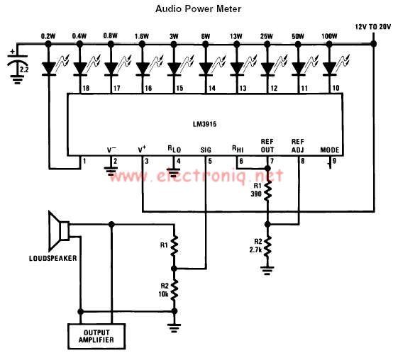
The LM3915 monolithic integrated circuit can be used to design a simple audio power level meter that senses analog voltage levels and drives ten LEDs, LCDs, or vacuum fluorescent displays, providing a logarithmic 3 dB/step analog display. One pin...
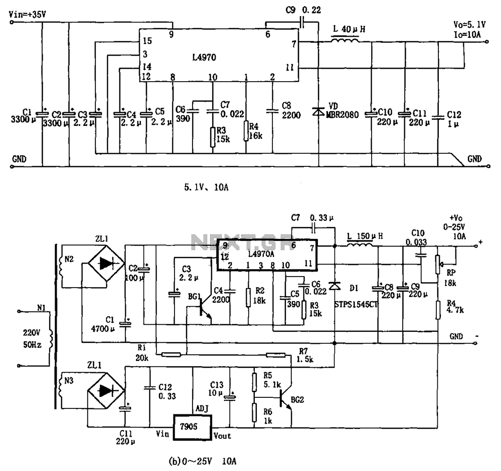
The L4970A power switching supply is a high-power monolithic integrated switching regulator, packaged in a SIP-15 format. It has specific characteristics: (1) The input voltage must be at least 11V, typically ranging from 15V to 40V; (2) The output...
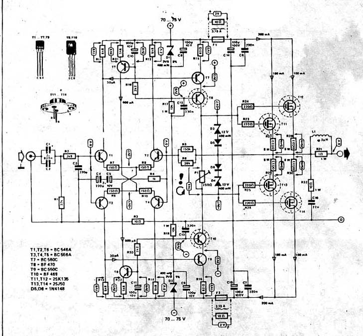
The power amplifier circuit utilizing MOSFET technology has gained significant popularity due to its aggressive sound characteristics when compared to traditional transistors and integrated circuits. It offers both low-frequency and high-frequency responses and is known for its durability. Generally,...

Useful circuit for self-powered speakers, radios, and TVs; can be used as a car power amplifier. Here is the schematic for an 8-watt audio power amplifier. The described circuit serves as an 8-watt audio power amplifier, suitable for various applications,...