
5W 7Mhz Rf Power Amplifier Circuit

This RF amplifier circuit is intended for use in amateur radio applications, specifically targeting the 40-meter band, which is popular among amateur radio operators for its relatively long range and favorable propagation characteristics. The circuit's design incorporates toroidal inductors, which are favored for their efficiency and compact size, making them suitable for RF applications.
The input stage of the circuit requires a drive power of about 20 mW, which can typically be supplied by a low-power RF source, such as a transceiver or other signal generator. The 13-volt supply is essential for powering the active components of the circuit, which may include transistors or operational amplifiers, depending on the specific design implementation.
The schematic includes detailed part numbers for the toroidal cores, which are crucial for achieving the desired inductance and performance characteristics. Proper selection of these components is vital to ensure low losses and high efficiency in the RF output. The circuit may also incorporate additional filtering or matching networks to optimize the output for transmission and minimize signal distortion.
Overall, this circuit exemplifies a practical approach to RF amplification within the amateur radio spectrum, providing operators with a robust solution for generating adequate power levels for effective communication. Proper assembly and tuning of the circuit will be necessary to achieve optimal performance in the intended frequency range. The circuit, shown will produce up to 5-W RF output in the 40-m (7 MHz) amateur band. The coils shown are wound on toroidal cores (Armdon Associates Inc.). The part numbers are given in the schematic. The circuit requires about 20-mW drive and a 13-V supply.
Related Circuits
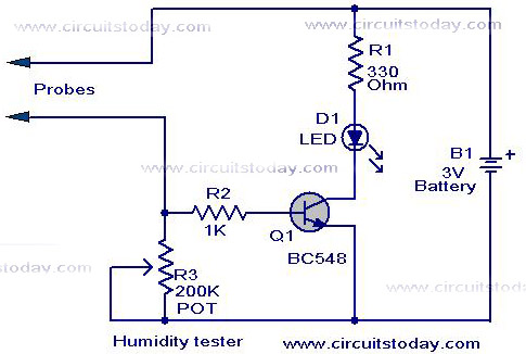
A simple humidity tester circuit using only an LED, a transistor, and a few resistors is explained with a clear circuit schematic. The humidity tester circuit is designed to provide a visual indication of humidity levels using basic electronic components....
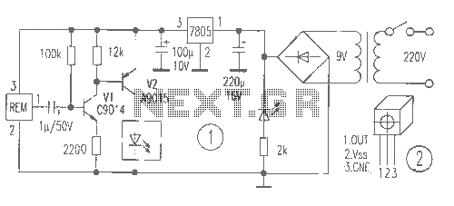
The receiver provides two TV signals, one for the living room and another for the bedroom, along with a satellite receiver. Watching television in the bedroom is convenient in Taiwan; however, when watching television in the living room, it...
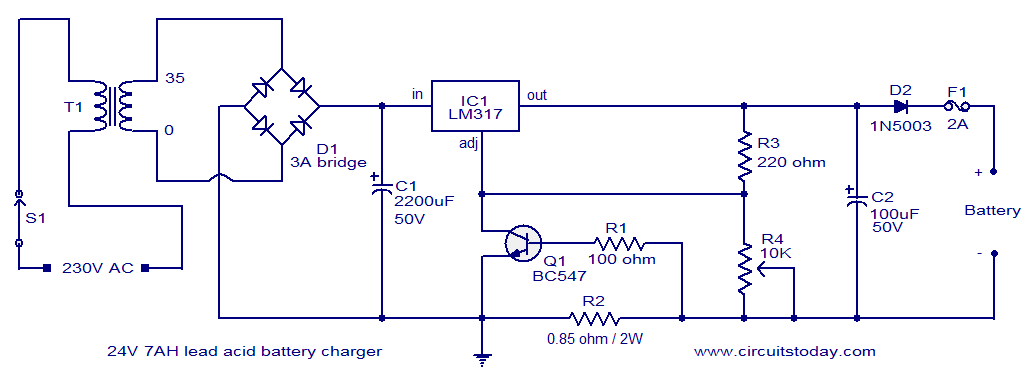
This lead-acid battery charger circuit is designed based on a request from Mr. Devdas C. His requirement was for a circuit that could charge two 12V/7AH lead-acid batteries connected in series. He did not specify the number of cells...
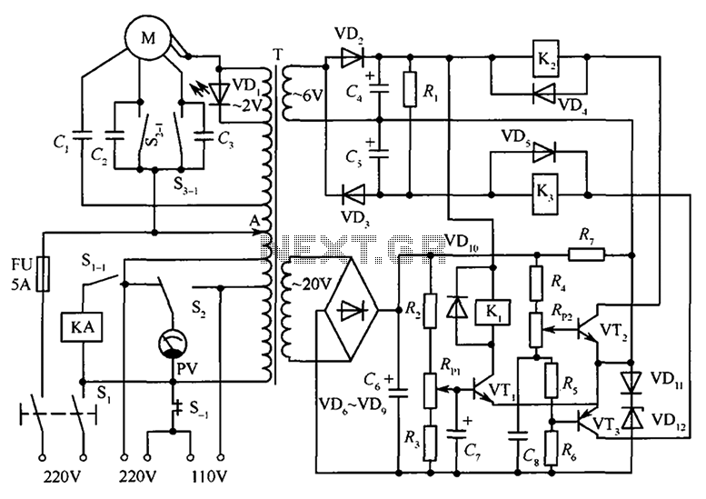
The circuit illustrated in the figure features an automatic voltage regulator (T) that utilizes a servo motor to ensure a constant output voltage. The transistors used are VT1 and VT2 (3DK9C, with a range of 65 to 85) and...
The search loop can be constructed in various ways; however, the method presented here should provide a solid foundation. Refer to Fig. 2 as a guide for assembling the loop. The loop should be made from non-metallic and moisture-resistant...
A two-tone generator that is alternately switched ON provides a high/low output similar to that of a traffic vehicle, such as a police car or ambulance. The CD4011 integrated circuit (IC1), which is a quad 2-input NAND gate, functions...