
60 watt guitar amplifier

This power amplifier circuit is designed for high-performance audio applications, particularly in guitar amplifiers, where sound quality and reliability are paramount. The use of a single-rail 60V supply simplifies the design and reduces the number of components, making it cost-effective and efficient. The capacitor coupling to the loudspeakers not only provides a high-pass filter effect but also protects the speakers from DC voltage, which can cause damage in case of a fault in the output stage.
The two-transistor gain block configuration enhances the amplifier's ability to handle high input signals without distortion, making it suitable for loud playing environments. The choice of transistors is critical; using MJ11014 and MJ11013 or TIP142 and TIP147 ensures that the amplifier can handle the power requirements without overheating or failing under load.
The selection of diodes D1 and D2 plays a significant role in the harmonic distortion characteristics of the amplifier. Schottky diodes offer fast switching and lower forward voltage drop, which can enhance performance, while the 1N4148 diodes provide a softer clipping characteristic, allowing for a more musical distortion when the amplifier is pushed to its limits.
Thermal management is a vital aspect of this design. The close thermal coupling of the sensing transistor (Q2) to the output transistors allows for accurate temperature compensation, ensuring that the amplifier operates reliably under varying load conditions. The use of a TO126 package for Q2 facilitates effective heat dissipation and simplifies assembly.
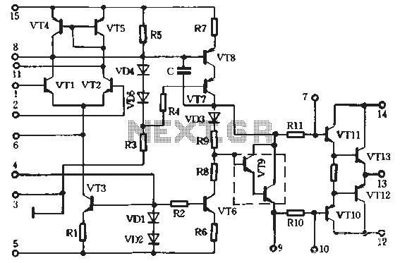
Finally, the adjustment of resistor R9 is crucial for achieving optimal performance. By measuring the voltage across capacitor C7, the designer can ensure that the output stage operates within its ideal parameters, preventing clipping and distortion at high output levels. Utilizing an oscilloscope for fine-tuning provides a visual representation of the waveform, allowing for precise adjustments to achieve the desired sound quality. This comprehensive design approach ensures that the amplifier meets the demands of both professional musicians and audio enthusiasts.This design adopts a well established circuit topology for the power amplifier, using a single-rail supply of about 60V and capacitor-coupling for the speaker(s). The advantages for a guitar amplifier are the very simple circuitry, even for comparatively high power outputs, and a certain built-in degree of loudspeaker protection, due to capacitor
C8, preventing the voltage supply to be conveyed into loudspeakers in case of output transistors` failure. The preamp is powered by the same 60V rails as the power amplifier, allowing to implement a two-transistors gain-block capable of delivering about 20V RMS output.
This provides a very high input overload capability. The Darlington transistor types listed could be too oversized for such a design. You can substitute them with MJ11014 (Q3) and MJ11013 (Q4) or TIP142 (Q3) and TIP147 (Q4). D1 and D2 can be any Schottky-barrier diode types. With these devices, the harmonic modifier operation will be hard. Using for D1 and D2 two common 1N4148 silicon diodes, the harmonic modifier operation will be softer. In all cases where Darlington transistors are used as the output devices it is essential that the sensing transistor (Q2) should be in as close thermal contact with the output transistors as possible.
Therefore a TO126-case transistor type was chosen for easy bolting on the heatsink, very close to the output pair. R9 must be trimmed in order to measure about half the voltage supply across the positive lead of C7 and ground.
A better setting can be done using an oscilloscope, in order to obtain a symmetrical clipping of the output wave form at maximum output power. 🔗 External reference
Related Circuits
A preferred STK4040xl Fi amplifier circuit exhibits excellent electrical parameters: under specific conditions, the output voltage (Uc) is 43V with a load resistance (RL) of 8 ohms. The circuit is designed to deliver a rated output power of at...
This Class E RF amplifier is capable of delivering up to 400 watts of RF output, depending on the input voltage and tuning parameters (current). The amplifier employs economical IXDD414 Driver ICs, with one driver for every two MOSFETs....
This project originated from a design requirement for a client, specifically for a microphone preamplifier intended for basic public address (PA) systems. The simplicity of this circuit makes it suitable for various applications where a mic preamp is needed,...
There is no substitute for sheer power—low-efficiency speakers, outdoor sound systems, or perhaps the full dynamic range of a high-power amplifier. Whatever the requirement, this super power module should meet the needs. The amplifier can be divided into three...
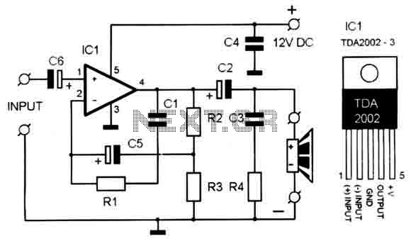
A compact, high-quality amplifier circuit that is also cost-effective. It utilizes the TDA2002, which provides very low distortion. The power supply should be between 12-15 volts at 1.2A. The amplifier's frequency response ranges from 40Hz to 15kHz. A suitable...
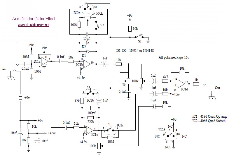
The Axe Grinder is designed with several key features in mind. It serves a wide range of distortion sounds by clipping part of the effect and allows users to overload their amplifier with a significantly boosted clean tone. The...