60W-225-400mhz-amplifier

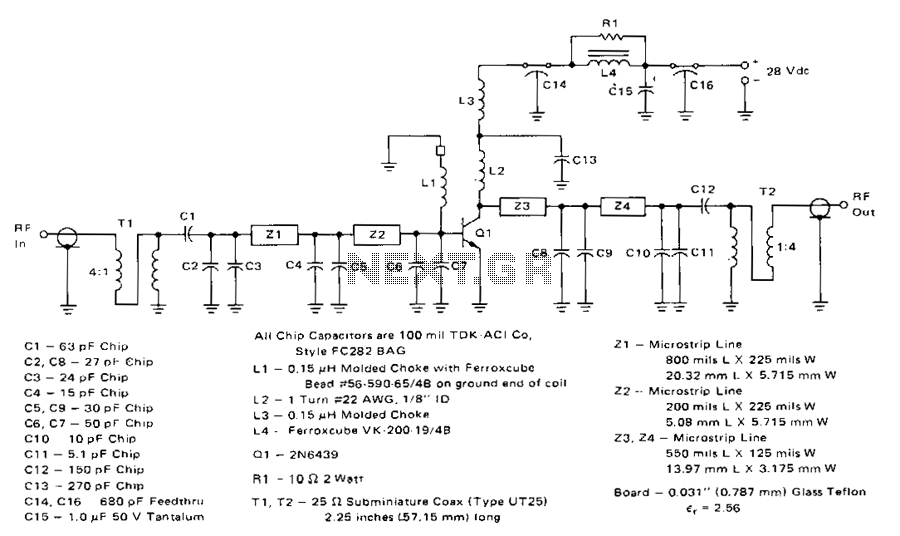
This 60-W, 28-V broadband amplifier operates within the 225-400 MHz military communications band. The amplifier can function independently as a 60-W output stage in a 225-400 MHz transmitter. Alternatively, by utilizing two of these amplifiers in conjunction with quadrature couplers, a 100-W output amplifier stage can be achieved. The circuit is designed to be driven from a 50-ohm source and to operate into a nominal 50-ohm load. The input network comprises two microstrip sections consisting of Z1, Z2, and capacitors C2 through C6. Capacitor C1 acts as a deblocking capacitor. A 4:1 impedance ratio coaxial transformer T1 completes the input matching network. Inductor L1 and a ferrite bead function as a base decoupling choke. The output circuit includes a shunt inductor at the collector, followed by two microstrip L-sections made up of Z3, Z4, and capacitors C8 through C11. Capacitor C12 serves as a deblocking capacitor and is succeeded by another 4:1 impedance ratio coaxial transformer. Collector decoupling is achieved using components L3, U, C14, C15, C16, and resistor R1.
The broadband amplifier is specifically designed for military communications, ensuring reliable performance across the specified frequency range. The input stage is carefully engineered with microstrip technology to minimize losses and achieve a high degree of impedance matching. The use of a 4:1 impedance ratio coaxial transformer allows for efficient power transfer from the source to the amplifier, optimizing the signal integrity.
The output stage is equally sophisticated, utilizing shunt inductors to manage the load impedance effectively. The two microstrip L-sections in the output network are crucial for further refining the output signal and ensuring that it meets the required specifications for transmission. Capacitors in the output circuit, including C12, provide necessary deblocking functions to prevent unwanted oscillations and maintain stable operation.
Decoupling is an essential aspect of this design, with the use of both inductors and capacitors to filter out noise and ensure that the amplifier operates smoothly under varying load conditions. The inclusion of ferrite beads in the base decoupling stage enhances the amplifier's stability by suppressing high-frequency noise that could interfere with performance.
Overall, this circuit design is a robust solution for military communication applications, offering flexibility in configuration while maintaining high efficiency and reliability. The approach taken in both the input and output stages reflects a deep understanding of RF amplifier design principles, ensuring that the device can effectively handle the demands of high-power transmission in challenging environments.This 60-W. 28-V broadband amplifier covers the 225-400 MHz military communications band. The amplifier may be used singly as a 60-W output stage in a 225-400 MHz transmitter. or by using two of these amplifiers combined with quadrature couplers, a 100-W output amplifier stage can be constructed. The circuit is designed to be driven from a 50-0 source and work into a nominal 50-0 load. The input network consists of two microstrip 1-sections composed of Z1, Z2, and C2 through C6. C1 serves as a deblocking capacitor. A 4:1 impedance ratio coaxial transformer T1 completes the input matching network. L1 and a ferrite bead serve as a base decoupling choke. The output circuit consists of shunt inductor 12 at the collector, followed by two microstrip L-sections composed of Z3, Z4, and C8 through Cl1. C12 serves as a de blocking capacitor, and is followed by another 4:1 impedance ratio coaxial transformer.
Collector decoupling is accomplished through the use of 13, U, C14, C15, C16, and Rl.