
8051SBC USB & GLCD Expansion Board

The 8051SBC USB and GLCD Expansion Board is designed to enhance the functionality of the 8051 microcontroller system by providing additional interfaces and capabilities. This board typically includes a USB interface for communication with external devices and a Graphic Liquid Crystal Display (GLCD) for visual output.
The schematic wiring diagram of the 8051SBC USB and GLCD Expansion Board outlines the connections between the microcontroller and various components such as the USB interface, GLCD, power supply, and other peripherals. The USB interface allows for data transfer and programming capabilities, enabling users to connect the microcontroller to computers or other USB-enabled devices. The GLCD provides a graphical interface for displaying information, making it suitable for applications requiring user interaction or data visualization.
In terms of power management, the board may include voltage regulators to ensure that the microcontroller and connected devices receive stable operating voltages. Additionally, the schematic may depict the arrangement of resistors, capacitors, and other passive components that support signal integrity and power distribution across the board.
Overall, the 8051SBC USB and GLCD Expansion Board serves as a versatile platform for developing projects that require both data processing and graphical output, making it an essential tool for engineers and hobbyists working with the 8051 microcontroller.8051SBC USB & GLCD Expansion Board, Electronic Circuit Schematic Wiring Diagram, 8051SBC USB & GLCD Expansion Board. 🔗 External reference
Related Circuits
A board design intended for measuring a load cell has been identified with a system accuracy fault traced to the amplifier integrated circuit (IC). The output of the amplifier IC changes when the board is twisted, yielding +80mV when...

This page provides links to software and hardware designs contributed by Handy Board users. If you would like to contribute some work of your own to the Handy Board community, please contact Fred Martin. George Musser contributed an adaptation...
The layout control motherboard is designed to facilitate the management of various sections of a layout. It features a microcontroller that connects to the MRNet bus and multiple slots for inexpensive control and sensor boards. All control and sensor...
A device that provides a USB port is recognized as a "CP2103 USB to UART Bridge Controller" when connected to a Windows PC. According to the device documentation, it communicates in serial format at 38400 bps. The USB pinout...
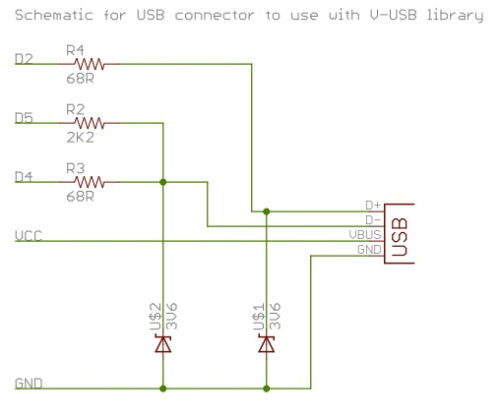
To successfully complete this project, it is necessary to construct the circuit as illustrated or as previously demonstrated. While the construction process is straightforward, any errors may prevent the V-USB software from functioning properly, potentially resulting in project failure....
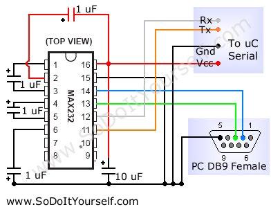
Bold lines indicate soldered connections, while arrows represent wire-based connections. Red indicates V_cc, black represents ground, blue signifies intermediate connections, and gold denotes the primary output. Pins 1 and 5 are connected to ground. It is noted that pin...