
877 ~ 924MHz RF2152 power amplifier the circuit diagram

The RF2152 is a high-performance power amplifier designed for applications in the 877 to 924 MHz frequency range. This amplifier is typically used in various RF communication systems, including wireless networks and mobile communication devices.
The circuit diagram of the RF2152 power amplifier includes several key components to ensure efficient operation and signal integrity. The amplifier is typically powered by a suitable DC voltage source, which is connected to the Vcc pin. The device is designed to provide a significant gain while maintaining linearity, which is crucial for minimizing distortion in the transmitted signal.
Input matching networks are often employed at the input stage to optimize the impedance seen by the RF signal source, enhancing the power transfer to the amplifier. These matching networks may consist of inductors and capacitors configured to resonate at the desired frequency.
The output stage of the RF2152 includes a load matching network to ensure that the output impedance is compatible with the subsequent stage or antenna. This network is designed to maximize power transfer and minimize reflections, which can degrade performance.
Thermal management is also a critical aspect of the design, as power amplifiers generate heat during operation. Heat sinks or thermal pads may be utilized to dissipate heat effectively, ensuring the device operates within its specified temperature range.
Overall, the RF2152 power amplifier circuit is designed to provide robust performance in the specified frequency range, with careful consideration given to input and output matching, thermal management, and linearity to ensure high-quality signal amplification.877 ~ 924MHz RF2152 power amplifier constituting the circuit diagram:
Related Circuits
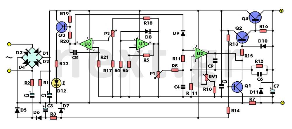
The left side of the circuit features the secondary winding of a 220V (primary) to 18V (secondary) / 3 Amp mains transformer. The 18V alternating voltage from the transformer’s secondary is rectified by diodes D1, D2, D3, and D4,...
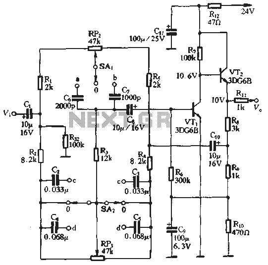
An attenuation switch is utilized to modify the pitch of a feedback control circuit's transition frequency, specifically for two treble controls. RP3 is designated for bass control, while SA1 and SA2 are employed to adjust the high bass control...
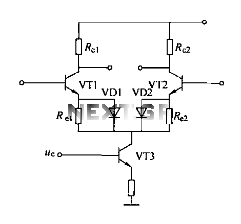
A controllable gain amplifier functions as an automatic gain control circuit within the execution unit. The primary methods for controlling the amplifier's gain involve two approaches: one is by adjusting certain parameters of the amplifier itself, such as emitter...
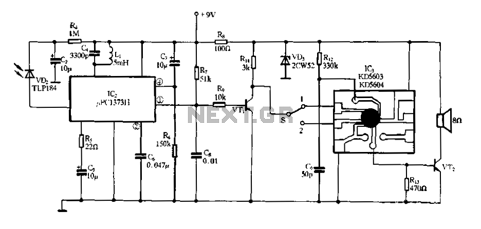
Electronic Miss Manners infrared receiver and voice circuits The Electronic Miss Manners system integrates an infrared (IR) receiver with voice circuits to facilitate communication and interaction. The IR receiver is designed to detect signals emitted from a remote control or...
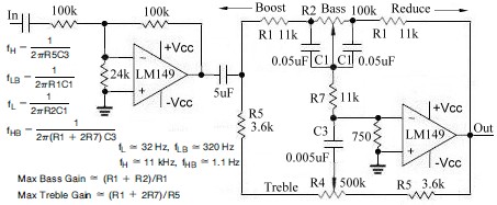
This topic continues from the more general Passive Tone Control circuit, which begins using only passive filters. This circuit follows the previous design, although the component values are different and in an alternate configuration. An audio tone control combines...
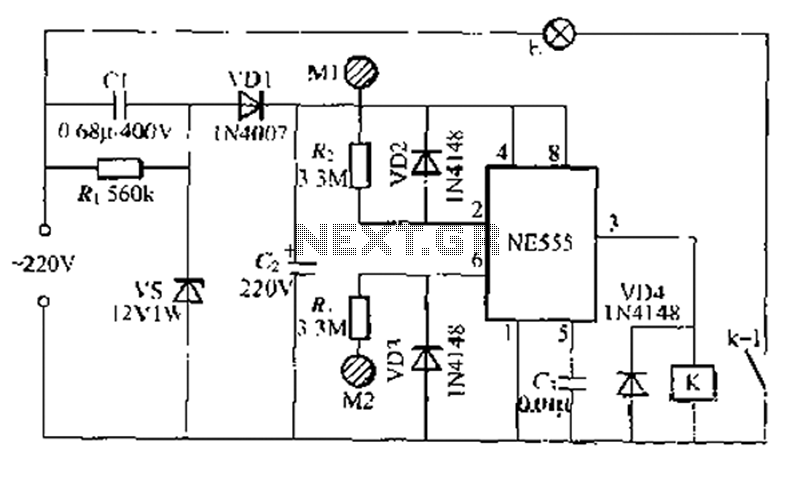
A use NF double touch lamp circuit based on a 55 base design, utilizing switches. It operates with 220V AC and includes a simple composition of a power-saving buck converter in conjunction with a half-bridge circuit. The circuit is...