
9 Volt 2 Amp Power Supply

The circuit utilizes a 78S09 voltage regulator, which is designed to convert a higher input voltage to a stable output of 9V. This regulator is capable of delivering a maximum current of 2A, making it suitable for various applications requiring moderate power levels. The low noise output characteristic of the 78S09 is particularly advantageous in sensitive electronic applications where signal integrity is crucial.
To enhance circuit reliability, a 1N5400 diode is positioned at the input. This component serves as a reverse polarity protection mechanism, preventing damage to the regulator and downstream components in the event that the power supply is connected incorrectly. The inclusion of C1, a smoothing capacitor, further stabilizes the input voltage by filtering out ripples and transient disturbances, ensuring that the regulator receives a clean input.
The output stage of the circuit includes C2, which serves as a filtering capacitor to reduce output voltage fluctuations and improve stability. For applications that involve powering digital logic circuits, the addition of a 100nF ceramic capacitor is recommended. This capacitor effectively filters out high-frequency noise generated by switching activities within the logic circuits, thereby enhancing overall performance and preventing interference.
In summary, this circuit is a robust solution for providing a stable 9V output, with built-in protections and filtering mechanisms to ensure reliable operation in various electronic applications. The careful selection of components and their arrangement within the circuit design contribute to its effectiveness and reliability.There is little to be said about this circuit. All the work is done by the regulator. The 78S09 can deliver up to 2 amps continuous output whilst maintaining a low noise and very well regulated supply. The circuit will work without the extra components, but for reverse polarity protection a 1N5400 diode is provided at the input, extra smoothing be
ing provided by C1. The output stage includes C2 for extra filtering, if powering a logic circuit than a 100nF capacitor is also desirable to remove any high frequency switching noise. 🔗 External reference
Related Circuits
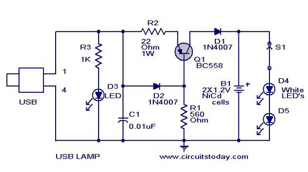
A simple USB LED lamp circuit utilizing a 5-volt power supply sourced from a USB port, designed to illuminate a desktop or laptop computer during power outages. The USB LED lamp circuit operates by converting the 5-volt DC power provided...
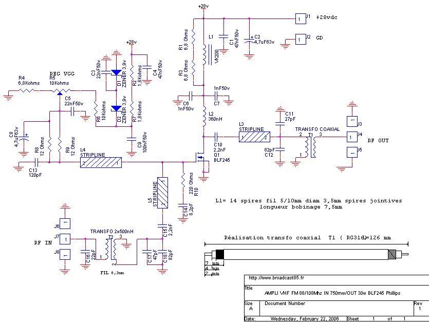
This FM 88-108 MHz radio amplifier is equipped with a BLF 245 and can be used with a heatsink from a processor and cooler. The BLF 245 datasheet can be downloaded. The FM 88-108 MHz radio amplifier utilizing the BLF...
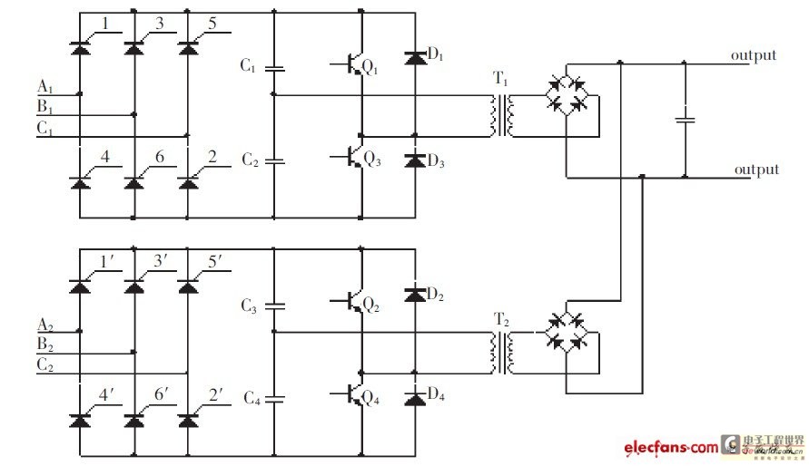
The high-pressure direct current power supply has become increasingly widespread. This system outputs in parallel with double-channel power to achieve low ripple direct current. In situations where gas switching tube frequency is limited, this method can generate low ripple...
The most effective way to understand space-charge tubes is to examine actual circuits. Review the online circuits provided below, and check if any older print articles are available from friends or personal collections. After familiarizing yourself with the material,...
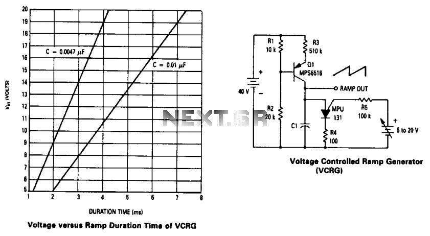
The current source created by Q1 in combination with capacitor C1 determines the duration of the ramp. As the positive DC voltage at the gate varies, the peak point firing voltage of the Programmable Unidirectional Thyristor (PUT) is altered,...
This article provides a comprehensive overview of the methodology used for testing power supplies (PSUs) in three main sections. The first section outlines the PSU parameters that are evaluated and specifies the testing conditions. The second section defines commonly...