
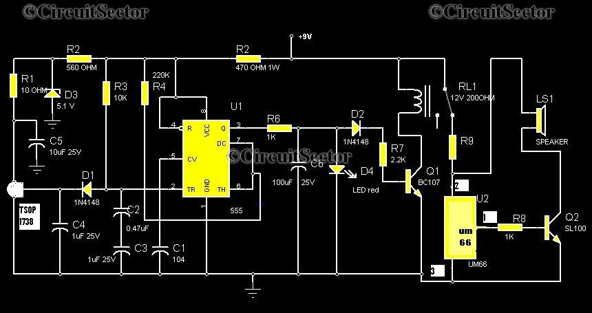
9V Power Supply For Garage Shed Alarm

The 9V power supply circuit for the garage shed alarm is designed to provide a stable voltage source for the operation of the alarm system. This circuit typically consists of a transformer, a rectifier, and a voltage regulator to ensure that the output voltage remains constant at 9 volts, even with variations in input voltage or load conditions.
The transformer steps down the AC mains voltage to a lower AC voltage suitable for the rectification process. Following this, the rectifier converts the AC voltage to pulsating DC voltage. A smoothing capacitor is often included in the circuit to reduce the ripple in the DC output, providing a more stable voltage level.
To ensure the output voltage does not exceed 9V, a voltage regulator is integrated into the circuit. This component maintains the output voltage at a fixed level, regardless of fluctuations in input voltage or load current. The regulator may be a linear type, such as the 7809 voltage regulator, which is commonly used for such applications.
The alarm circuit itself is designed as a single-zone burglar alarm, meaning it monitors a single area for unauthorized entry. It typically includes a motion detector or door/window sensors that trigger the alarm when an intruder is detected. The alarm may be an audible siren or a visual indicator, such as flashing lights, to alert the owner of a breach.
In summary, this circuit combines a reliable 9V power supply with a single-zone burglar alarm system, making it suitable for use in a garage shed or similar environments, ensuring both security and functionality.The following circuit shows about 9V Power Supply For Garage Shed Alarm Circuit Diagram. Features:single-zone burglar alarm circuit, used with the .. 🔗 External reference
Related Circuits
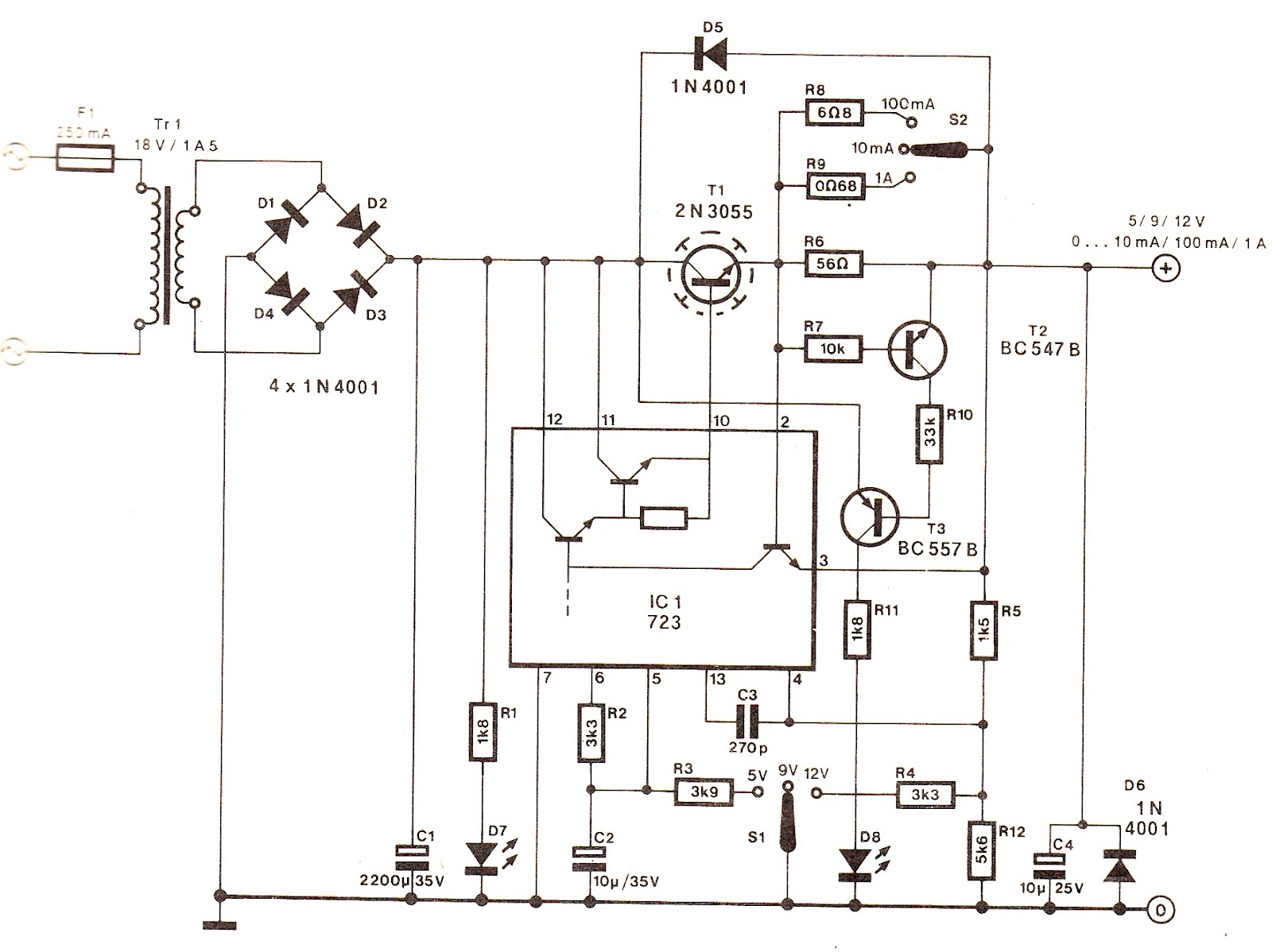
The output voltage can be increased easily by placing a resistor in parallel with Ra until it reaches precisely 5.0 V. Switches S1 and S2 are preferably SPDT types with a center position, but three-way rotary switches can also...
Numerous circuits are available for infrared burglar alarms; however, the transmitter section of these circuits can be complex and may require assembly. This burglar alarm circuit utilizes a standard DVD remote as the transmitter, which reduces both cost and...
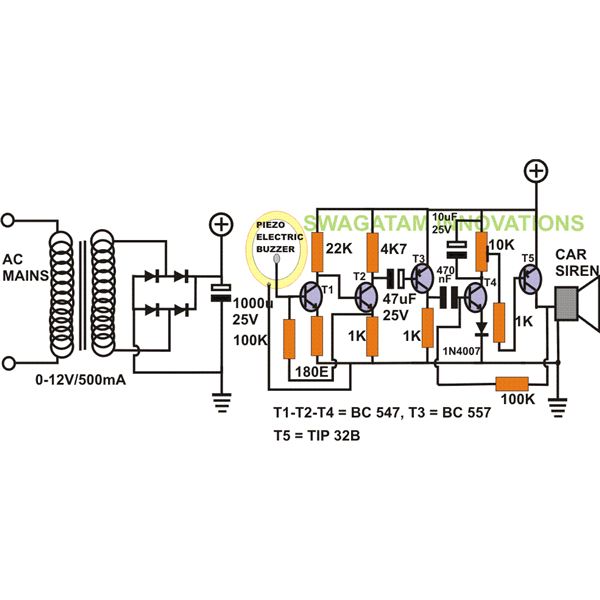
The project "DIY: Build a Sound Activated Switch" presented here is straightforward to construct and can be very useful in protecting a specific area from potential theft or intrusion. Learn how to build a simple sound-activated alarm here on...
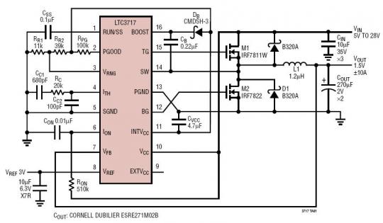
The LTC3717 is a synchronous step-down switching regulator controller designed for double data rate (DDR) and Quad Data Rate (QDR) memory termination. It utilizes a valley current control architecture to achieve very low duty cycles without the need for...

A simple lab power supply electronic project can be designed using this circuit diagram, which is based on the LM2576 monolithic integrated regulator that provides all the active functions for a step-down (buck) switching regulator. As seen in the...
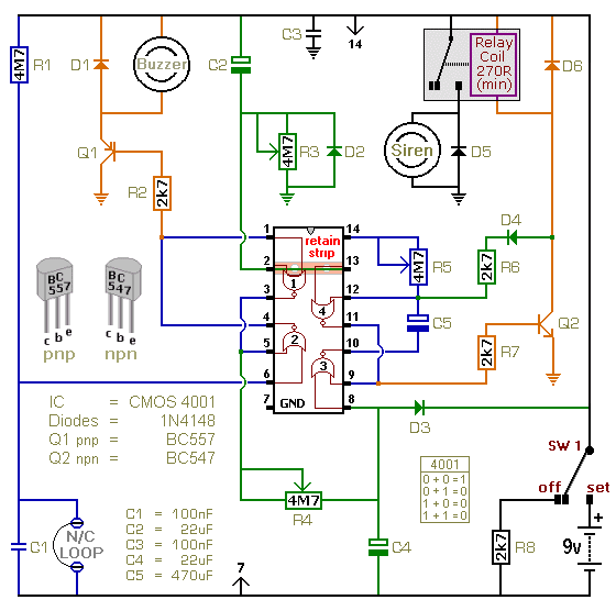
This is a single-zone alarm system featuring independently adjustable Exit, Entry, and Siren Cut-Off timers. It is designed to accommodate standard normally-closed input devices, such as magnetic reed contacts, foil tape, and passive infrared sensors (PIRs). The system can...