
A bedside lamp delay circuit

The circuit operates with a CD4 component that serves as the heart of the design. The Vcc terminal provides the necessary voltage for the entire circuit, while the ground terminal establishes a common return path for the current. The reset terminal is crucial for initializing the circuit, ensuring that it starts from a known state. The Qt and Q terminals are used for output control, where the Q terminal indicates the current state of the SCR.
The inclusion of an external resistor oscillation element allows the circuit to generate a specific frequency, which is essential for controlling the blinking of the light source. The capacitor C4 plays a vital role in determining the oscillation frequency along with the resistors, specifically R4 and additional resistors connected in the circuit. The oscillation frequency is calculated using the formula that incorporates the capacitance of C4 and the resistance values, facilitating precise control over the blinking rate.
When the button is pressed, the SCR is triggered, allowing current to flow through the light source, which can be a light-emitting diode or another type of lamp. The SCR remains in a conductive state, sustaining the light until the reset condition is activated or the power is removed. The blinking pattern is controlled by the timing circuit, which includes the resistor and capacitor combination. The frequency of the blinking is set to a cycle of approximately 0.25 seconds, with a specific on/off duration that creates a visually appealing flickering effect.
The design also considers safety and efficiency, ensuring that the circuit does not draw excessive power when idle. The resistance and capacitance values are selected to optimize the performance of the circuit while maintaining low power consumption. Overall, the circuit provides a reliable and efficient solution for controlling light sources through oscillation and SCR technology.1C is a CD4 cries O. A (16) feet for the Vcc terminal. (8) feet for the ground. (12) feet for the reset terminal. (7) feet for Qt end, (3) feet to q. End (Sh, U). (Il) FW exter nal resistor oscillation element pit. Taipa deposit C4 oscillation frequency electric power to Yin pair alum. w decisions; credible f Deputy: in the off state annals, but also of a circuit, especially when more power when you press 1 button AN, towels electric converter provided by Rii trigger current to be in vain silicon SCR, SCR guide larva, light teal. Indole this state, r bubble across the electric Ju through c. Drop Ng, Di plow stream, after DW regulator, in c/nitric end was holy to the galvanic about IOV. L rG role. 1C is reset to zero. (3). cn feet are the output fW: ratF. Corresponding to the three diodes day deadline G, c commanded by end DC R7, Ri. I continue to make the SCR conduction. [C-zero, the oscillator starts to oscillate within stationary oscillation frequency is about 1./2.3C4(R4+W).
Correspondence (7) feet have connected a light emitting tube flicker. t resistance adjusting chop most A.fl.t. He vibration cycle is about 0.25 seconds, and also delay of about a tip of T4-h 0.25, BD 33 Clocks the blinking cycle of the arc tube is 24 x O. 25 seconds, that is 4 seconds l on for 2 seconds and off for 2 seconds). W l value transferred dish drawer hours, the oscillation period of approximately 0023 seconds, and the extension of the hemp called about 3 Shu bell, then pq sparkle cycle arc tube about 0 4 seconds, L uf to see this.
It flashes the speed of light arms delay mountain when I can reflect the length Austin. To delay time, (3) Gallery lose HI high, BG saturation. SCR trigger current water Further Oh Ge off. Results Zhu light is off, the delay circuit also stop working without electricity, resistance R, capacitance C, providing electricity to close down the road.
Related Circuits
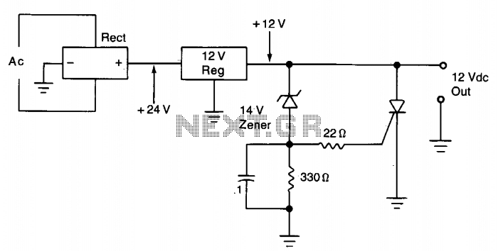
The silicon controlled rectifier (SCR) is designed to handle at least the current provided by the power supply. It is connected in parallel across the 12 V DC output lines but remains inactive until a voltage is applied to...
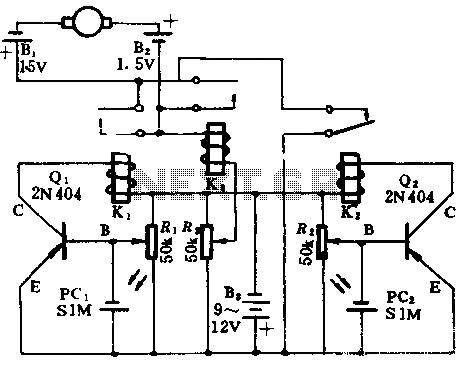
In the absence of light, photocells PC1 and PC2 exhibit high resistance, causing transistors Q1 and Q2 to remain off, which prevents the relay contacts K1 and K2 from closing. The battery B3 is connected through a potentiometer Rs,...
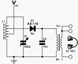
Currently, the most commonly available headphones have an impedance ranging from 2 to 32 ohms. This relatively low value renders them unsuitable for certain designs. However, with some clever modifications, these headphones can be effectively utilized in such applications....
S1 and S2 are normally open, push-to-close, momentary switches. The diodes can be either red or green and are used solely for indicating direction. The TIP31 transistors may need to be adjusted based on the motor specifications. It is...

This article discusses a simple 5-channel radio remote control circuit utilizing the TX-2B and RX-2B integrated circuits from Silan Semiconductors. The TX-2B/RX-2B is a remote encoder-decoder pair suitable for remote control applications. It features five channels, a wide operating...
A USB port is capable of supplying more than 100 mA of continuous electric current at 5V to peripherals connected to the bus. This feature allows a USB port to power 5V DC-operated small electronic devices without issues. Many...