
A circuit diagram of the filter by the transistor

A band-pass filter is an essential electronic circuit that allows signals within a certain frequency range to pass while attenuating frequencies outside that range. The circuit typically consists of a combination of resistors, capacitors, and transistors configured to achieve the desired frequency response.
In a transistor-based band-pass filter, the transistors serve as active components that enhance the filter's performance by providing gain, which is crucial for maintaining signal integrity. The design typically incorporates both high-pass and low-pass filter sections, which are connected in such a way that the output only allows a specific band of frequencies to be transmitted.
The schematic usually includes two stages: the first stage is a high-pass filter formed by a capacitor in series with the input signal and a resistor connected to ground. This stage blocks low-frequency signals. The second stage is a low-pass filter, which consists of a resistor in series with the output and a capacitor connected to ground, effectively blocking high-frequency signals. The cutoff frequencies of these two stages determine the bandwidth of the filter.
Transistors in the circuit are often configured in a common emitter or common collector arrangement, depending on the required gain and impedance characteristics. The selection of transistor types, along with the values of resistors and capacitors, is critical to achieving the desired filter characteristics, including center frequency, bandwidth, and roll-off rate.
Careful consideration of the layout and component placement is also important to minimize parasitic capacitance and inductance, which can adversely affect filter performance. Proper biasing of the transistors ensures optimal operation and stability across the desired frequency range.
Overall, a well-designed band-pass filter using transistors can effectively isolate specific frequency components in a signal, making it a valuable tool in various applications, including audio processing, communications, and signal conditioning.Described in this article is a band-pass filter is a circuit diagram of transistors, as shown below.
Related Circuits
This is a voltage doubling circuit built using the well-known timer IC 555. The circuit is straightforward and easy to construct. The construction is not critical. Rectifier diodes should be ultrafast (such as UF4004 or similar), or 1N4148 signal...
Research has been conducted on a project aimed at enhancing understanding of electronics, networking, and programming. The project involves the construction of an online thermometer suitable for applications requiring temperature monitoring. The current work environment is a laboratory where...
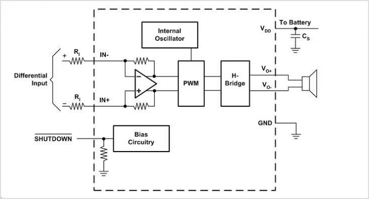
The EUA2123 is a highly efficient Class-D audio power amplifier capable of delivering up to 20W into a 4-ohm load in stereo mode using a single-ended (SE) configuration, or up to 40W into an 8-ohm load in mono mode...
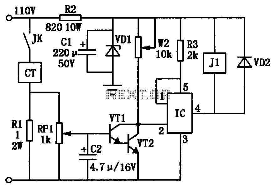
The circuit depicted in the figure utilizes a +24V power supply derived from a 110V power source through an electromagnetic chuck. When the electromagnetic chuck circuit is activated, the contact JK closes, enabling the operation of the magnetic chuck....
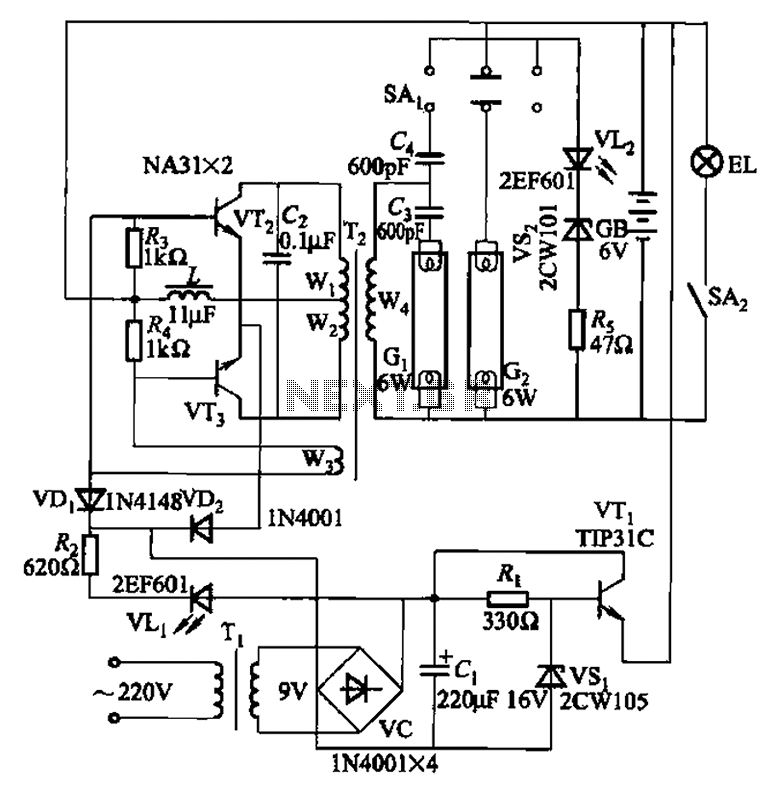
This is a Nissan Panasonic rechargeable emergency fluorescent lamp circuit. It features built-in 6V, 4Ah high-energy batteries that can be directly charged. The circuit supports two 6W fluorescent lamps. It includes functional switches SAi and SAz. When SAi is...
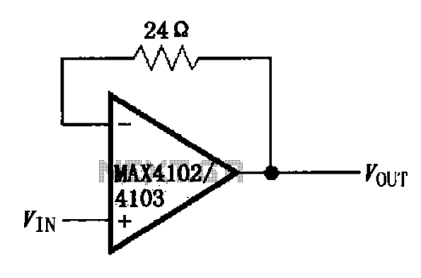
The MAX4102/4103 unity gain buffer circuit is illustrated in the figure. This circuit incorporates a small resistor (24 ohms) positioned in the feedback loop of the amplifier, which forms a unity gain buffer. Additionally, it achieves a maximum bandwidth...