
A Cmos 4060 Burglar Alarm

The CMOS 4060-based burglar alarm circuit is designed to provide a reliable security solution for a single zone. The primary component, the CMOS 4060 IC, serves as a timer and oscillator, enabling the circuit to manage various functionalities such as exit and entry delays, along with siren activation and deactivation.
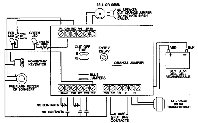
The circuit typically consists of several key elements: the CMOS 4060 IC, a power supply, input devices (such as magnetic reed switches), a siren or alarm output, and additional passive components like resistors and capacitors. The magnetic reed switches act as the normally-closed input devices that trigger the alarm when opened.
Upon activation, the CMOS 4060 generates a timing signal that initiates the exit delay, allowing users to leave the premises without triggering the alarm. After the exit delay, the system enters an armed state. If any of the input devices are opened during the armed state, the alarm is triggered, activating the siren.
The entry delay is also managed by the CMOS 4060, allowing users to disarm the system after entering the premises. Once the user enters the designated time frame, the alarm will deactivate, provided the correct disarm procedure is followed.
The siren cut-off timer is a crucial feature that prevents the siren from sounding indefinitely. After a predetermined time, the siren will automatically turn off, reducing the risk of nuisance alarms and ensuring that the system remains user-friendly.
In summary, the CMOS 4060 burglar alarm circuit is an effective and versatile solution for enhancing security in a single zone, providing automatic timers for exit, entry, and siren cut-off, while accommodating various input devices.A Cmos 4060 Burglar Alarm Circuit This is a single zone alarm - with automatic exit, entry and siren cut-off timers. It will accommodate all the usual types of normally-closed input devices - such as magnetic-reed contacts - foi..
🔗 External reference
Related Circuits

The following circuit is a simple, inexpensive, and easy-to-build motorcycle alarm. The circuit requires only two transistors to drive a relay, which acts as a switch to activate a buzzer. Any number of normally-open switches can be used. Mercury...

This circuit utilizes a 555 timer integrated circuit (IC) to function as an alarm system designed to deter theft of personal belongings, such as luggage, or to prevent unauthorized entry into a residence. The alarm is activated when a...

A digital mains failure and resumption alarm circuit utilizes an optocoupler to generate an audible sound. This circuit diagram includes a description of various alarm circuits for digital mains failure. The digital mains failure and resumption alarm circuit is designed...

Beeper and/or LED remotely-operated via mains supply line. Pressing the pushbutton of the transmitter, a sound and/or light alert is activated in the receiver. The system uses no wiring or radio frequencies: the transmitted signal is conveyed into the...

Motorcycle Alarm Number 4. This is a simple, easy-to-build, transistor-based motorcycle alarm. It is designed to operate at 12 volts; however, it can be adapted by changing the relay to a different specification. This motorcycle alarm circuit utilizes a transistor...
The following alarm circuit is designed with features that may be suitable for residential and commercial alarm system applications. It has a 12V and 1.5A regulated power supply. Furthermore, this residential alarm circuit also includes a delay circuit, a...