
A Friendly Charger Schematic for Mobile Phones

The design of this charging circuit is critical for ensuring the longevity and safety of mobile phone batteries. The integration of voltage and current regulation prevents overcharging, which can lead to battery damage or reduced lifespan. By maintaining a charging current of around 180mA, the circuit adheres to the recommended slow charging practices, thereby minimizing heat generation and enhancing battery health.
The over-current protection mechanism is particularly important in scenarios where the battery may develop faults or when there is a short circuit. The use of resistor R8 not only helps in sensing over-current conditions but also plays a crucial role in determining the maximum charging current. Adjusting R7 allows for fine-tuning of the charging current to suit different battery specifications or user preferences.
The inclusion of a ten-second delay before reactivation post power failure is a thoughtful design element that mitigates the risk of damage from voltage spikes. This feature ensures that the mobile phone is not subjected to sudden surges, which could potentially harm its internal circuitry.
In terms of physical construction, utilizing a common PCB allows for a compact design that can easily fit within a small plastic case. This not only makes the circuit portable but also protects the components from environmental factors.
Overall, this circuit serves as an effective solution for mobile charging, providing essential protective features while ensuring efficient battery charging practices. Proper assembly and connection are vital for the successful operation of this circuit, emphasizing the importance of attention to detail in electronic design.Most mobile chargers do not have current/voltage regulation or short-circuit protection. These chargers provide raw 6-12V DC for charging the battery pack. Most of the mobile phone battery packs have a rating of 3. 6V, 650mAh. For increasing the life of the battery, slow charging at low current is advisable. Six to ten hours of charging at 150-200m A current is a suitable option. This will prevent heating up of the battery and extend its life. The circuit described here, provides around 180mA current at 5. 6V and protects the mobile phone from unexpected voltage fluctuations that develop on the mains line. So the charger can be left on` over night to replenish the battery charge. The circuit protects the mobile phone as well as the charger by immediately disconnecting the output when it senses a voltage surge or a short circuit in the battery pack or connector.
It can be called a middle man` between the existing charger and the mobile phone. It has features like voltage and current regulation, over-current protection, and high- and low-voltage cut-off. An added specialty of the circuit is that it incorporates a short delay of ten seconds to switch on when mains resumes following a power failure.
This protects the mobile phone from instant voltage spikes. When short-circuit occurs at the battery terminal, resistor R8 senses the over-current, allowing Q1 to conduct and light up D1. Glowing of D2 indicates the charging mode, while D1 indicates short-circuit or over-current status. The value of resistor R8 is important to get the desired current level to operate the cut-off. With the given value of R8 (3. 3 ohms), it is 350 mA. Charging current can also be changed by increasing or decreasing the value of R7 using the I=V/R` rule.
Construct the circuit on a common PCB and house in a small plastic case. Connect the circuit between the output lines of the charger and the input pins of the mobile phone with correct polarity. We aim to transmit more information by carrying articles. Please send us an E-mail to wanghuali@hqew. net within 15 days if we are involved in the problems of article content, copyright or other problems.
We will delete it soon. 🔗 External reference
Related Circuits
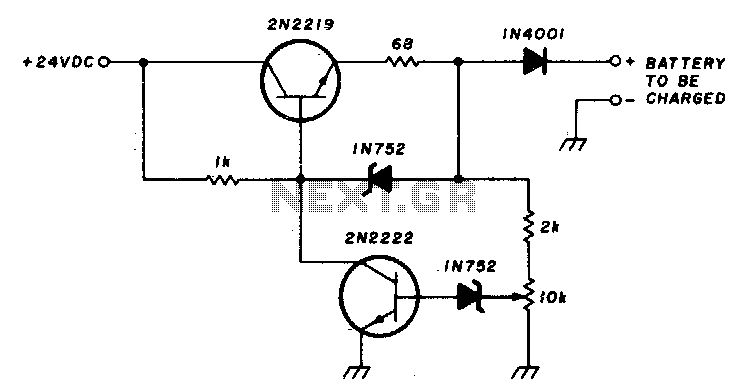
This circuit charges a battery at a rate of 75 mA, allowing the battery to remain in the charger indefinitely until fully charged. Once the battery reaches its full charge, the circuit reduces the current to a trickle rate....
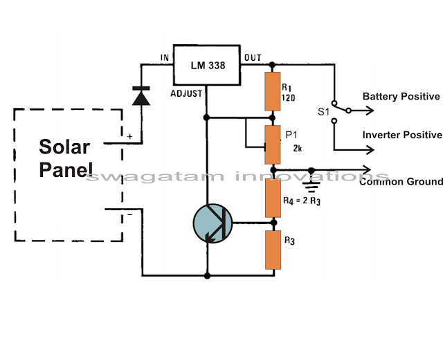
Solar panels are well-known devices that convert solar energy or sunlight into electricity. A solar panel consists of discrete sections of individual photovoltaic cells, each capable of generating a small amount of electrical power, typically between 1.5 to 3...
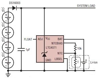
A simple solar-powered battery charger circuit can be designed using the LTC4071 Li-Ion/Polymer Shunt Battery Charger System with Low Battery Disconnect. When VCC reaches the programmed float voltage (4.1V with ADJ floating), the LTC4071 shunts excess current not used...
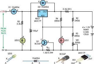
Although not a new device, the LM317 is still a high-performance regulator. Its output voltage is essentially immune to fluctuations in load and supply voltage. The LM317 is a versatile adjustable linear voltage regulator widely used in various electronic applications....
This is a minimal circuit designed for individual audio amplifier projects to control the presenter output relay. The purpose of this circuit is to manage the relay that activates the speaker output within the audio amplifier. The circuit introduces...
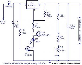
The circuit is designed as a constant voltage source with a negative temperature coefficient. The transistor Q1 (BD 140) serves as the temperature sensor, while transistor Q2 prevents battery discharge through resistor R1 when mains power is unavailable. The...