
A receiving converter for 2320 MHz

The preamplifier circuit employs the MGA86563 low-noise amplifier, which is designed for high-frequency applications, ensuring minimal noise contribution while maintaining strong signal amplification. The internal matching of the input and output ports to 50 ohms simplifies integration with standard RF components. The inclusion of capacitors before and after the amplifier is crucial for DC blocking and ensuring that the amplifier operates correctly within its specified voltage range.
The use of a 100-ohm resistor serves a dual purpose: it stabilizes the circuit by reducing the quality factor (Q) and prevents unwanted oscillations that could compromise performance. The design's reliance on a quarter-wave stripline for power supply routing minimizes potential interference and loss, enhancing overall circuit reliability.
The harmonic mixer, constructed with Schottky diodes, efficiently converts the RF signal by mixing it with the local oscillator frequency, while the bandpass filter effectively suppresses unwanted image frequencies, ensuring that only the desired signal is processed. The ERA 3 amplifier further boosts the signal, which is particularly beneficial in applications where signal strength is critical, such as in satellite communications.
The choice of a phase-locked loop for the local oscillator provides frequency stability, although the design's limitations in achieving optimal sideband noise performance suggest a need for careful selection of oscillator components. The recommendation to utilize established designs for local oscillator generation reflects best practices in RF circuit design, ensuring reliable operation in various environments.
In summary, this circuit design illustrates a well-thought-out approach to RF amplification and mixing, balancing performance with component availability and cost considerations. The successful operation of the converter at 13 cm demonstrates its effectiveness in practical applications, making it a viable option for amateur radio enthusiasts and other users requiring reliable RF signal processing.The preamplifier is very simple. I used a Low Noise integrated circuit manufactured by Hewlett Packard. The device name is MGA86563. It has a Noise Figure of about 2dB and can be used from 0. 5 GHz to at least 6 GHz. The gain is about 20-22dB at 2. 3 GHz. The input and output ports are internally matched to 50 Ohms. All you have to do is to put a ca pacitor in front of the device and behind it and provide the necessary supply voltage of 5-7 Volts at the output port. I used a quarterwave stripline for the supply voltage. The 100 Ohms resistor is used to "de-Q" the circuit in order to avoid oscillations. This resistor causes a voltage drop that must be equalized by a somewhat higher supply voltage of 7. 5 Volts. (Fig. 2) The harmonic mixer is not much more than two Schottky Diodes BA481. They short circuit the signal twice at every periode of the LO signal (at every half-wave). At the input there is a bandpass filter to suppress the image frequency. A monolitic amplifier ERA 3 from Mini Circuits (New York) amplifies the signal for another 20dB. This is not necessary in order to have an optimal sensitivity (the preamp would be sufficient without another amplifier) but it helps to have a strong signal at 144 MHz.
This allows you to put the converter at the antenna and use a cheap coax cable for the IF. A 144 MHz amplifier at the output is not advisible because strong 144MHz-signals from the neighborhood could get into the amplifier and then cause interference to your 13cm signal. The LC-transformation-circuit at the output makes sure that the mixer is not overloaded by the 50 Ohms of the IF receiver.
(Fig. 3) I will not give the circuit diagram for the 1088 MHz local oscillator. It is really not adviceable the way I did it (now I know!). I built a 1088 MHz VCO and phase-locked it using a MC74HC4046 phase comparator and a U893 prescaler. As a reverence oscillator I needed a 17 MHz oscillator but I could not get a 17 MHz crystal. So I used a 12 MHz crystal oscillator and mixed the signal using a NE612 with an adapted 5 MHz crystal. After filtering the 17 MHz-signal I was able to feed it into the 74HC4046 phase comparator. The circuit works good so far, but the sideband noise of the oscillator signal is not half as good as that of a multiplied crystal signal.
Despite the fact that I used a high cut-off frequency for the PLL low pass filter the oscillator signal is still a little bit noisy. So I suggest that you use one of the many circuits that are available for 23cm converters. They produce a LO signal of 1152 MHz by multiplying a 96 MHz crystal oscillator by 12. If you use a 90. 667 MHz crystal you get 1088 MHz. An output of 5mW will be very fine but 2mW will also work well. (You don`t have to have a lot of harmonics in your signal because there are two diodes in the mixer. I would work well even if your LO signal would be 100% clean. ) The converter works just fine here at my station. We have compared the sensitivity to that of comercially built converters and were not able to detect any difference.
If I use SSB I do not notice the LO sideband noise. (That is why several amateurs use this kind of LO for satellite reception at 13cm. ) When listening to FM signals from my friends in the neighborhood the audio signal is always a little bit noisy even if the signals are strong enough. 🔗 External reference
Related Circuits
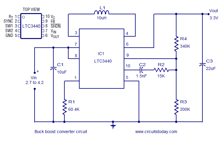
A highly efficient buck-boost converter circuit is presented, utilizing the LTC3440 buck-boost regulator IC from Linear Technology. This IC requires only one inductor and achieves efficiency levels of up to 96%. For applications where the output voltage is below...
This is a PIN diode-based RF signal attenuator circuit that operates with input frequencies ranging from 1 MHz to 500 MHz. PIN diodes are among the most commonly used components in RF applications. The RF signal attenuator circuit utilizing PIN...
The RF amplifier is similar to the one used in the 2.5 MHz amplifier. At a frequency of 10 MHz, the capacitances of a power MOSFET become significant. Noiseless feedback using transformers is no longer straightforward. Intermodulation and overtones...
This circuit is very simple, consisting of fewer than 12 components, designed to build a DC to AC converter. The principle of this circuit involves generating a 50/60Hz frequency using the IC CD4047. The output from pins 10 and...
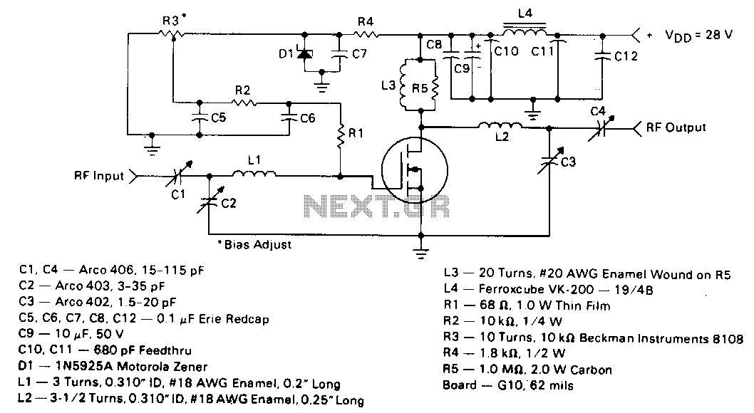
This circuit employs the MRF123 TMOS power FET. The MRF134 is a high-gain FET that may exhibit instability at both VHF and UHF frequencies. A 68-ohm input loading resistor has been used to improve stability. This amplifier achieves a...
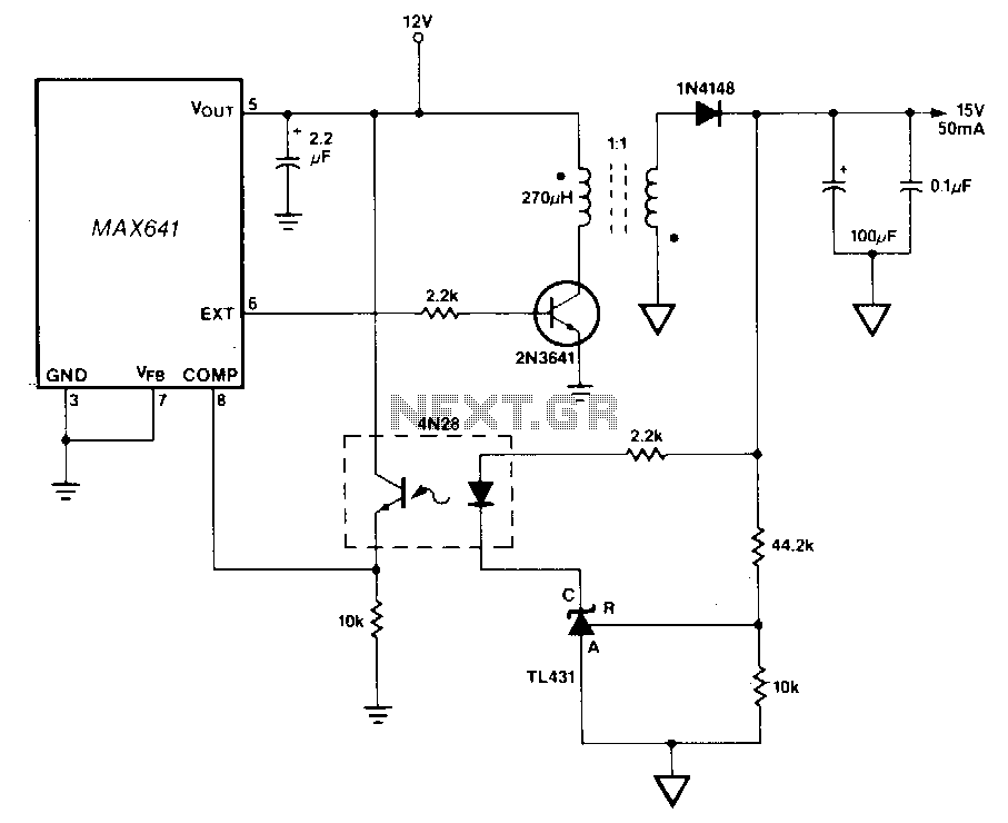
In this circuit, a TU31 shunt regulator is utilized to monitor the output voltage. The TU31 activates the LED of a 4N28 optocoupler, which delivers feedback to the MAX641 while ensuring isolation between the input voltage of +12 V...