
A Regenerative Receiver with AGC for 80 and 40 Meters

The AGC-80/40 receiver's design emphasizes simplicity and effectiveness in its operation. The use of varactor tuning through rectifier diodes not only reduces component count but also enhances reliability by minimizing mechanical wear associated with traditional variable capacitors. The implementation of Automatic Gain Control ensures stable reception across varying signal strengths, which is particularly beneficial in amateur radio applications where signal conditions can fluctuate significantly.
The passive filtering stages contribute to the overall audio quality, allowing for clear voice communication and effective CW reception. The choice of low-pass filter frequencies is carefully considered to accommodate the typical bandwidth requirements of voice and CW signals, ensuring that the receiver remains versatile in its applications.
In summary, the AGC-80/40 represents a thoughtful evolution of the AGC-80 design, maintaining a commitment to simplicity while incorporating advanced features such as AGC and switched-capacitor tuning. The careful selection of components and design choices reflects a deep understanding of radio frequency principles, making this receiver an excellent choice for amateur radio enthusiasts seeking a reliable and effective regenerative receiver for the 40 and 80-meter bands.Here`s a dual-band Regen that came from some encouraging emails from Jerry (K9UT) and another gentleman named Harvey, who built my original AGC-80, and its experimental "Regenerodyne" successor, the AGC-80/30. Jerry and I have corresponded on several occasions, and he tells me that he enjoys both receivers and that they work surprisingly well for
such simple circuits. A few other Hams have written to express their satisfaction with the AGC-80 as well. Many thanks to those of you who gave me helpful feedback. Jerry asked me when I was going to design an AGC-controlled Regen for 40 meters. I pointed out that I had already posted two other 40 meter receivers at my webpage, but neither has AGC. So Jerry`s request led to this project, the AGC-80/40. This is a successor to the original AGC-80, a Colpitts-based Regenerative receiver with audio-derived AGC [Automatic Gain Control] to prevent strong signals from "pulling" or "blocking" the detector.
Like its predecessor, it is `varactor`-tuned [actually I use rectifier diodes as varactors] and has no bulky, expensive variable capacitors. Actually, the AGC-80 did have a pcb-mounted trimmer cap that calibrated the front panel, setting the band limits.
This new receiver does away even with that trimmer cap. Bandswitching is accomplished by a double-pole, double throw toggle switch that switches capacitance values in the "front end" where the signal comes in from the antenna, and simultaneously switches coils (wound on small toroid cores) in the Regen Detector stage, for 80 and 40 meter operation. The receiver also uses passive filtering with switched capacitance values to kill the extreme highs with a 2500 Hz lowpass filter for voice transmissions, or an 800 Hz peaked lowpass filter for receiving CW transmissions.
I probably should have - and may in the future, if I decide to sell this receiver as a kit - add an internal audio amp and speaker; right now, I route the audio to a front-panel jack and into my trusty old Radio Shack Amplified Speaker (see the photos in the AGC-80 article). The following is an in-depth description of the AGC-80/40 circuitry, which I installed in a nice little metal box made by Hammond; see photos near the end of this article.
Radio signals present at the BNC jack (see Front End schematic, below) are brought into the receiver front end across a 1Kohm resistor whose job is simply to dissipate any static charges, that might be present on the antenna, to ground. Since the impedance looking into the front end of the receiver is 50 ohms, this 1K is "invisible" to the normal functioning of the circuit.
The front-end "Pre-selector" is a simple series L-C circuit consisting of L1, an Amidon T50-2 red-gray toroid core wound with 40 turns of #28 enamelled copper "magnet" wire (sold by Radio Shack) and having an inductance of about 7. 4 microhenries, and a 68pF silver mica capacitor, for the 40 meter band [7. 0 - 7. 3 MHz]. [This is a revision; the first release of this receiver on 7/14/08 had a 3-winding antenna transformer, but I found that going back to the same series L-C that I used in the original AGC-80, worked better in this receiver too.
] When the bandswitch is flipped from 40m to 80m, another 220 pF of capacitance is connected in parallel with the 68 pF cap, increasing the total capacitance to 288 pF and lowering the circuit`s resonant frequency to the 80 meter band [3. 5 - 4. 0 MHz]. This is a very simple preselect and bandswitching arrangement that works best with a 50 ohm antenna. I use a `resonant` antenna tuner to accomplish impedance matching and to get some extra "preselect" bandpass filtering via the tuner.
Originally, I was going to have a tuneable "preselector" up front, like the one on my old Drake 2B commercial receiver - but I wanted to stay true to my goal of having NO variable capacitors anywhere in the radio. So I went with the switched-capacitor method which required the use of a DP 🔗 External reference
Related Circuits
There is a vast array of TX and RX modules available for microcontrollers. The least expensive option identified was priced at $9.99, which is reasonable, although there are memories of encountering FM receiver modules in the past. The TX (transmitter)...
This web page is a memorial to Mike Caughran, KL7R, who passed away unexpectedly in January 2007. Mike was an enthusiastic experimenter, well-regarded in the homebrew radio electronics community. He is best known as the co-creator and collaborator with...
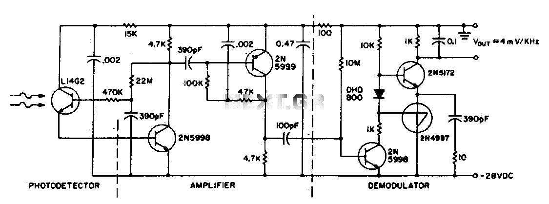
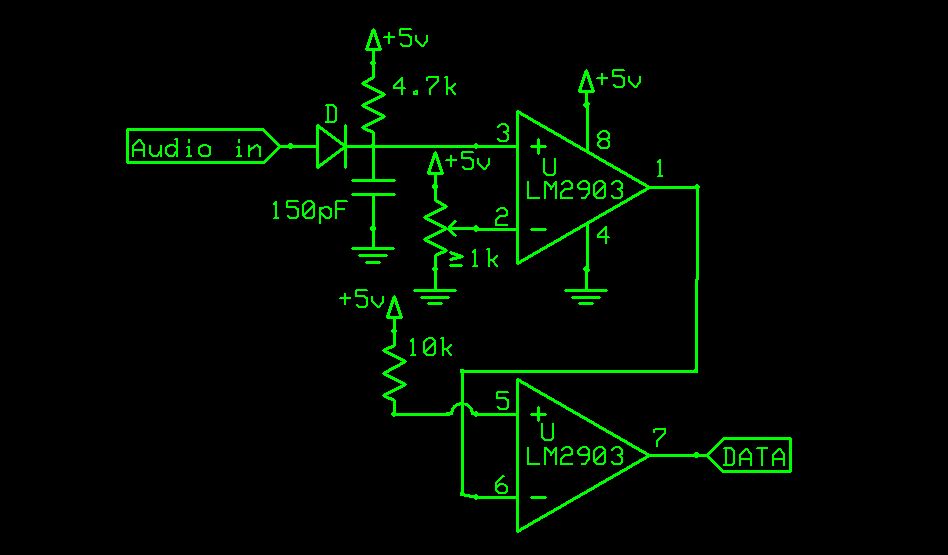
This circuit consists of an L14G2 detector, two stages of gain, and an FM demodulator. Better sensitivity can be obtained using more stages of stabilized gain with automatic gain control (AGC). The circuit design features an L14G2 detector, which serves...
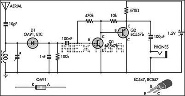
This circuit is an amplified crystal set. The inductor can be a standard AM radio ferrite rod antenna, while the tuning capacitor is a variable plastic dielectric gang designed for small AM radios. The aerial tuned circuit feeds diode...
The following is a translation of a section from the first book of the three-part series "Die Röhre im UKW Empfang" edited by Dr. Ing. Horst Rothe in 1952. This section describes a fully differential super-regenerative self-limiting FM detector....
This compact receiver is slightly larger than an AA battery. It is powered by two LR44 button cells, which are relatively costly and may not have a long lifespan. There is an intention to search for LR44 batteries at...