
A tube amplifier 01 HI-FI

The circuit described operates within a power supply system designed for aircraft applications, where reliability and performance are critical. The output transformer’s frequency response is particularly notable for its low distortion across the specified range, which is essential for audio and signal integrity in high-fidelity applications. The rectifier bridges, constructed from 1N4007 diodes, are robust components capable of handling high reverse voltages, ensuring that the system can operate under various load conditions without failure.
The configuration of resistors and capacitors plays a vital role in maintaining voltage stability and preventing overshoot during transient conditions. The use of a Darlington pair (VT1 and VT2) provides a high current gain, allowing the circuit to drive loads more effectively while maintaining a stable output voltage. The choice of high-voltage transistors (2SC3306 and 2SC3743) indicates that the circuit is designed to handle significant power levels, making it suitable for demanding applications.
The filtering capacitors (C7 and C9) are strategically placed to mitigate high-frequency noise that could interfere with the performance of the power supply. This noise filtering is crucial in sensitive electronic environments, such as those found in aircraft systems, where electromagnetic interference can adversely affect operation.
Overall, the circuit exemplifies advanced engineering practices, utilizing high-quality components and thoughtful design to achieve a reliable and efficient power supply solution for aviation applications.As a result of high quality materials and advanced technology, the machine output transformer frequency response can reach 10Hz (a 0.8dB) ~ 50Hz (a ldB), to improve the overall index basis. Aircraft power supply voltage section shown in Figure 1-42 in each group, three rectifier bridges are constituted by the four 1N4007, Rl ,. R2 is Cl, C2. C3 and C4 are resistors, two capacitors connected in series in order to prevent Because a partial pressure caused by uneven overvoltage.
Following is used to achieve high-voltage electrical delay control, the machine uses its normally open contact groups. R3 is power resistors, since the relay Kl output between the output and the VT1 have 500v - 360V-140V pressure, so affixed R3 to reduce the requirements for VT1 tube, R3 take 60V (40mA a R4 taken 82kn C6 take lO fiF.
It used to reduce grain output .VD13 ~ VD15 crossing the regulator diode, electrical voltage to around 360V o VT1, VT2 connected in Darlington form, to get a better voltage regulation review C7 and C9 filter high frequency wave capacitors, and R3 taken o.lrdrFpR5 like to share power, R5 taken 1.5kfl.R6 take 82kfl + C7 with R4 a C 5.VT1, VT2 uses high-voltage power transistor 2SC3306, VT3 as the power transistor 2SC3743
Related Circuits
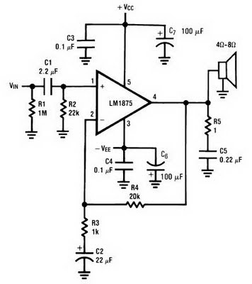
The amplifier circuit can be constructed using the LM1875 power amplifier IC. The LM1875 is a single-chip power amplifier from National Semiconductor. This 20-watt audio amplifier is characterized by low power consumption while delivering high-quality sound suitable for use...
Any electronics amateur possessing a collection of vinyl recordings and seeking high-quality reproduction should construct this preamp and integrate it into the Modular Preamplifier chain. This circuit offers a very high input overload capability, low distortion, and precise reproduction...
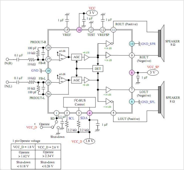
The AN41240A is a single-chip integrated circuit (IC) designed for audio applications. It employs a single-hall-sensor drive on the input side of the spindle motor drive block and utilizes a low-noise direct PWM drive of sine wave on the...

The AD8555 is a zero-drift sensor signal amplifier featuring digitally programmable gain and output offset. It is designed to effectively and accurately convert variable pressure sensor and strain bridge outputs into a well-defined output voltage range. Additionally, the AD8555...
The main part of this circuit is the LM386 amplifier chip. It also uses a transistor input to buffer the input signal and provide extra gain for the LM386. The little unit has helped me out on numerous occasions...
This low-cost project allows audio reproduction from a TV without disturbing others. It eliminates the need for wired connections between the TV and loudspeakers by utilizing invisible infrared light to transmit audio signals. Without the use of lenses, a...