Ac-circuit-breaker

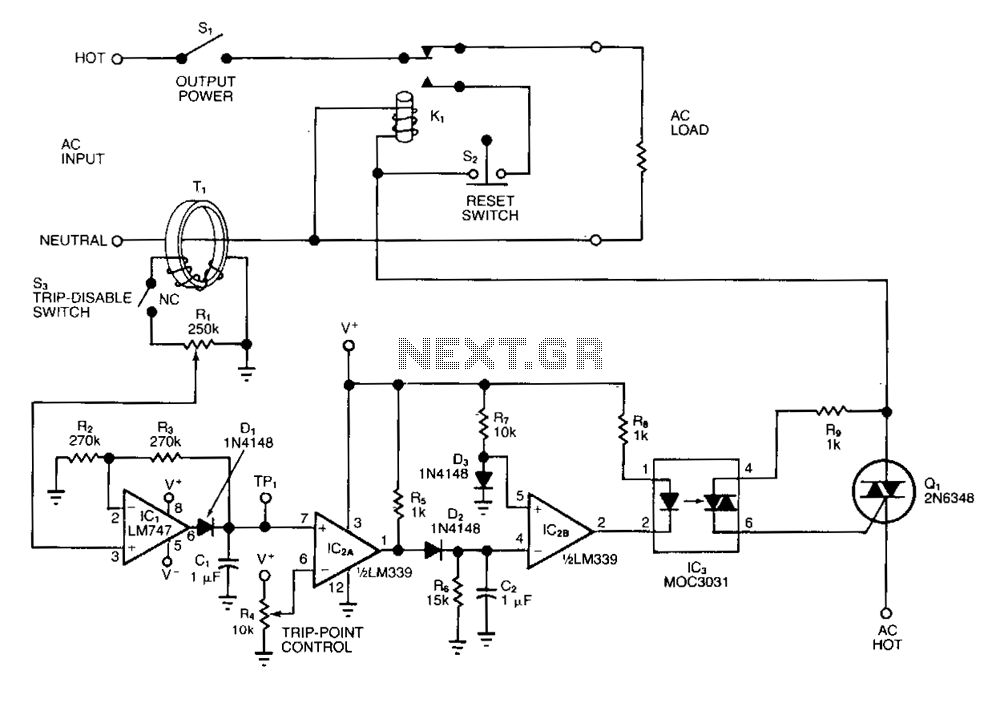
The adjustable circuit breaker responds in 0.02 seconds under all conditions, provided a fast relay is selected for K1. For moderate overload conditions, it is preferable to use a fuse or a fast-acting breaker. The toroidal transformer T1 senses AC load current and produces an AC signal at the wiper of R1 when switch S3 is closed. Diode D1 rectifies this signal to produce a positive voltage at test point TP1. R1 allows for calibration of this voltage, enabling the circuit to accommodate a variety of current-sense transformers. To calibrate the trip threshold, apply the maximum expected overload and adjust R1 until the TP1 voltage is 0.7 V below the positive saturation level for IC1. Then adjust R4 for the desired trip point. To reset the circuit breaker after it has tripped, open S1 or S2.
The adjustable circuit breaker described operates with a rapid response time of 0.02 seconds, contingent upon the selection of a fast relay for K1. This design is particularly advantageous for applications requiring quick disconnection under fault conditions. In scenarios involving moderate overloads, the inclusion of a fuse or a fast-acting breaker is recommended to safeguard against potential damage.
The circuit employs a toroidal transformer, T1, which is instrumental in monitoring the alternating current (AC) load. As the load current flows, T1 generates an AC signal that is transmitted to the wiper of resistor R1 when switch S3 is engaged. The AC signal is subsequently rectified by diode D1, converting it into a positive voltage that is available at test point TP1. The presence of resistor R1 plays a crucial role in calibrating this output voltage, allowing for flexibility in the use of various current-sense transformers, which may have differing output characteristics.
Calibration of the trip threshold is a critical step in ensuring the circuit operates within desired parameters. To achieve this, the maximum expected overload should be applied to the circuit. Adjustments to R1 are made until the voltage at TP1 reads 0.7 V below the positive saturation level for integrated circuit IC1. Following this calibration, resistor R4 is adjusted to establish the desired trip point, ensuring that the circuit breaker will activate appropriately under overload conditions.
Resetting the circuit breaker after a trip event is straightforward. The operator can reset the system by opening either switch S1 or S2, which will restore the circuit to its normal operating state. This design enhances the reliability and functionality of the circuit breaker, making it suitable for various applications where overload protection is essential.The adjustable circuit breaker responds in 0.02 sunder all conditions-provided you select a fast relay for Kl. For moderate overload conditions, it"s preferable to use the fuse or the fast-acting breaker. Toroid transformer Tl senses ac load current and produces an ac signal at the wiper of Rl, when switch S3 is closed.
Diode Dl rectifies this signal to produce a positive voltage at test point TPl. Because Rl allows you to calibrate this voltage, the circuit accommodates a variety of current-sense transformers. To calibrate the trip threshold, apply the maximum expected overload and adjust Rl until the TPl voltage is 0. 7 V below the positive saturation level for ICl. Then adjust R4 for the desired trip point. To reset the circuit breaker after it has tripped, open Sl or S2.