
AC power supply circuit

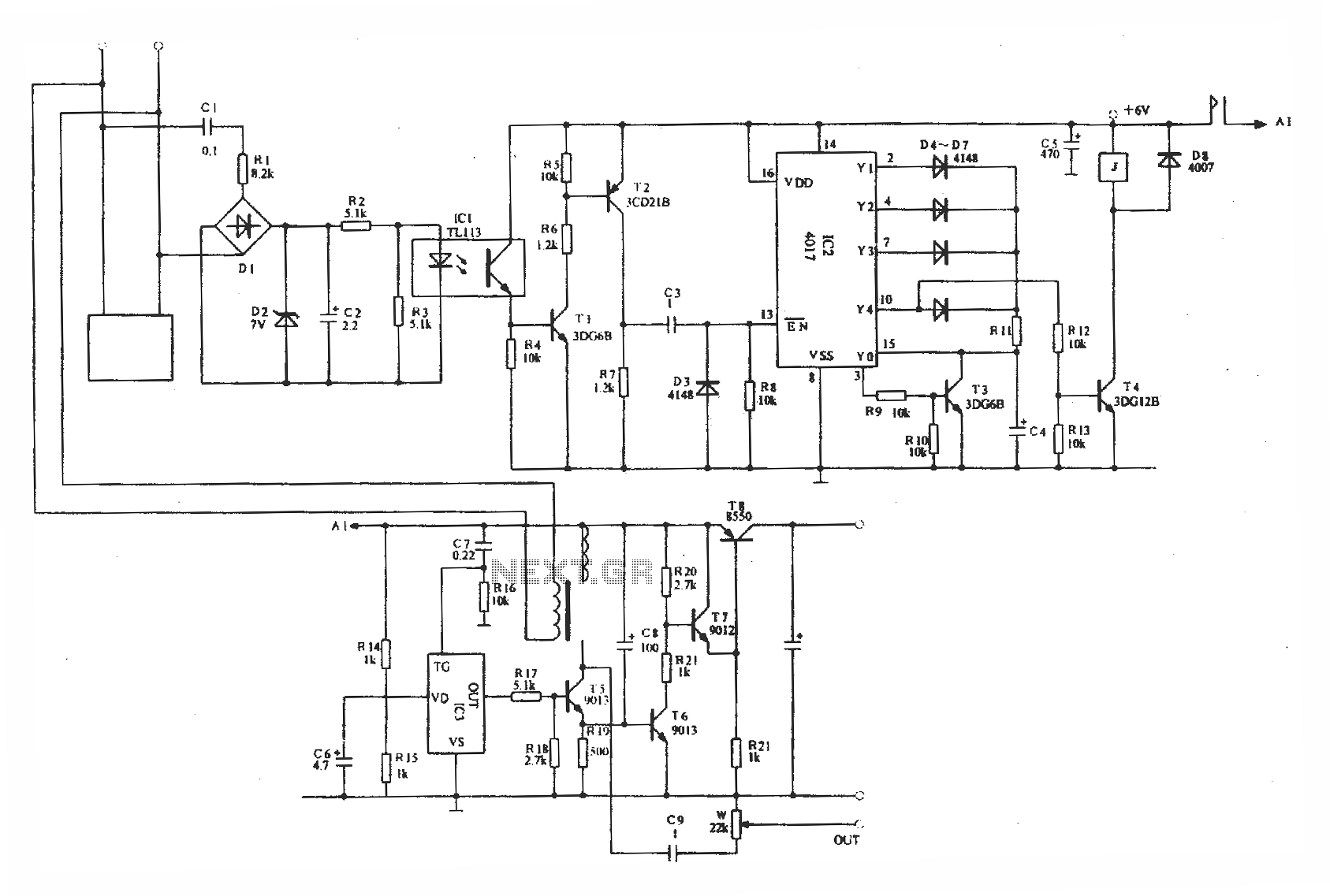
The AC power supply circuit operates by regulating the output voltage in response to fluctuations in the mains voltage. The circuit is designed to maintain a stable output through the use of voltage comparators and operational amplifiers. When the mains voltage is normal, the circuit ensures that the output remains at an optimal level, with point C providing a reference voltage of 3V.
In scenarios where the mains voltage drops, the system reacts by monitoring the voltage levels at points A and B. If point A drops below the threshold of 3V, it triggers the activation of transistor VT1, which in turn engages relay K1. This action adjusts the output of the regulator to 1.3V, ensuring that the load receives adequate power even during voltage dips.
As the voltage continues to fall, the circuit's feedback mechanism becomes critical. The voltage at point B is also monitored; if it drops below 3V, the output from U2 activates VT2, which engages relay K2. This process allows the regulator to adjust its output dynamically, compensating for the reduced input voltage.
On the other hand, if the mains voltage increases, the circuit is designed to respond by deactivating the relays. When point B surpasses the 3V threshold, AJ2 goes low, which turns off K2, allowing the system to stabilize and prevent overvoltage conditions. As the voltage at point A rises above 3V, AJ1 will cut off VT1, releasing relay K1 and allowing the output to adjust accordingly.
The use of IC1 as an integrated three-terminal device simplifies the design, providing a compact solution for powering the operational amplifiers and relays. Additionally, VD5 and VD6 serve as protective components, safeguarding the circuit from potential voltage spikes and ensuring reliable operation over time. This comprehensive design ensures that the AC power supply circuit remains effective in maintaining stable output across varying mains voltage conditions.AC power supply circuit as shown in FIG. It mainly consists of power supply, the reference voltage, the comparator voltage sampling circuit, and several other units. Mains tran sformer from O, feet input,, feet autotransformer tap,, feet for the control power supply circuit and sampling taps. Mains voltage is normal, because the voltage at point C is always 3V (ie Ri vs buck regulator income).
A, B point voltage greater than 3V, it J1, AJ2 output low level When the mains voltage drops,, pin voltage can be decreased, A point voltage drop also followed when the A point voltage drop low at 3V when, AJ1 output high, the transistor VT1 saturated conduction, the relay Kl warm together, the regulator output adjusted to 1,3 feet; when the mains voltage continues to drop while, empathy voltage at point B below 3V (UA
Related Circuits
A CD4017 is configured as a senary counter, with an input clock frequency of 300 Hz. Diodes VD1 to VD9 and resistors R1 to R3 form three three-input OR gates, which can each receive two 50 Hz three-phase wave...
Optically isolated phone automatic recording interface circuit, IC3 voice module. The optically isolated phone automatic recording interface circuit is designed to capture audio signals from a telephone line while ensuring electrical isolation between the phone line and the recording device....
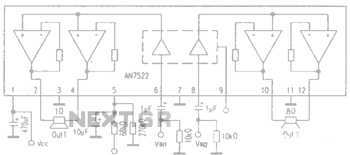
AN7522 is a Panasonic stereo audio amplifier IC that delivers an output power of 3W at 8 ohms. It features a standby function, low static power consumption, and reduced noise levels, requiring fewer external components for stable operation. This...
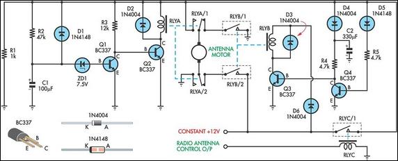
This up/down timer was designed to control a power antenna on a late-model vehicle. Normally, this vehicle uses a body computer to control the antenna. However, the owner intended to install a high-powered audio stereo system. The original stereo...
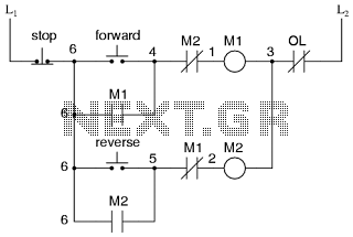
This is the power diagram for motor forward and reverse operation. To change the motor direction, one polarity must be altered, for example, changing R to S. For detailed information, please refer to the following. The described power diagram illustrates...
A simple audio amplifier application using a TL431 voltage regulator. The amplifier is designed to produce room-filling sound from a standard clear radio equipped with a long-wire antenna and suitable ground. The chip is similar in complexity to a...