
Access room people number counter circuit

The circuit operates based on the interruption of light beams emitted by the transmitters A and B, which are aimed at their respective photoresistors LDR1 and LDR2. When an object passes through the access channel, it obstructs the light path between the transmitter and receiver pair, resulting in a change in resistance of the photoresistor.
In practical terms, when light from source A strikes LDR1, it causes a decrease in its resistance, allowing current to flow through the circuit. This change can be detected by a microcontroller or a comparator circuit, which can trigger an output action, such as sounding an alarm or activating a gate mechanism. Similarly, when light from source B is interrupted, LDR2 experiences a change in resistance that can also be monitored.
The circuit can be designed to include additional components such as amplifiers to enhance the signal from the photoresistors, and logic gates to process the output signals more effectively. Power supply considerations should also be addressed to ensure that the light sources and the detection devices operate efficiently. Overall, this photoelectric detection system provides a reliable method for monitoring access channels in various applications, such as security systems or automated entry controls.Working principle: Two pairs of photoelectric detection devices are installed in the access channel. On one side the light source A (transmitter) and the photoresistor LDR1 (receiver) are installed in the entrance of the channel; on the other side, the light source B (transmitter) and the photoresistor LDR2 (receiver) are installed in the outlet of the chann.. 🔗 External reference
Related Circuits
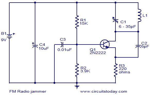
The FM jammer circuit diagram transmits VHF signals. Normally, the powerful oscillation of the circuit interrupts FM signals. Jammers are banned in many regions. The FM jammer circuit operates by generating a strong VHF (Very High Frequency) signal that disrupts...
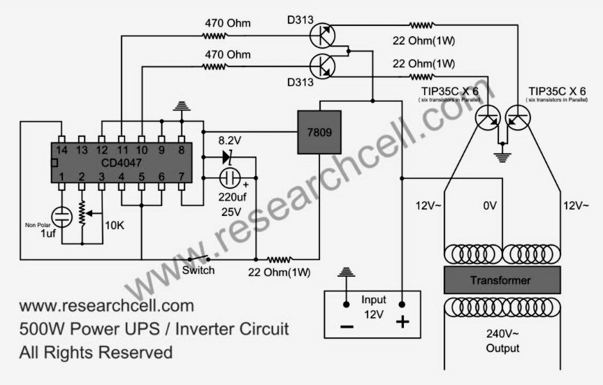
This circuit diagram features a single variable resistor utilized to adjust the frequency of a 240V AC output current. It is advisable to use a frequency meter to modify the frequency from 50Hz to 60Hz according to specific requirements....
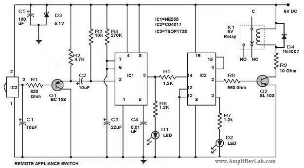
The circuit diagram of a remote-controlled appliance switch circuit includes two main components: IC1 (NE 555) and IC2 (CD 4017). The remote-controlled appliance switch circuit is designed to allow users to control electrical appliances wirelessly. The heart of this circuit...
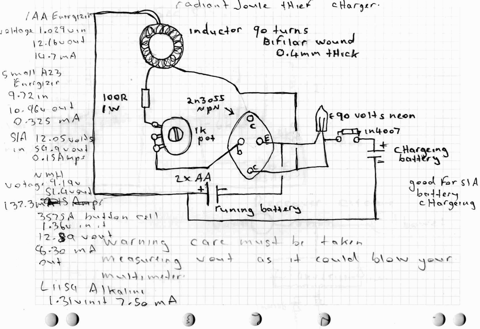
A high power joule thief circuit is explained in this post, which can be constructed by any new hobbyist. Here is the simplified drawing of the radiant joule thief battery charger. The inductor was wound with many turns until...
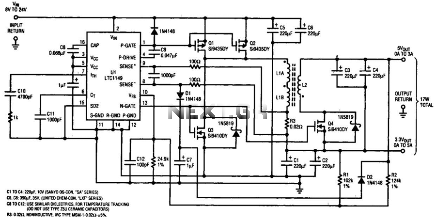
One LTC 1149 synchronous switching regulator can deliver both 3.3 and 5 V outputs. The design's simplicity, low cost, and high efficiency make it a strong contender for portable, battery-powered applications. The circuit described accepts input voltages from 8...

The circuit utilizes the MAX1576Y charge pump white LED driver, capable of supplying a total current of up to 480mA across two groups (n = 4 white LEDs). Each white LED in the flashing group can draw a maximum...