Accurate-variable-gain-circuit

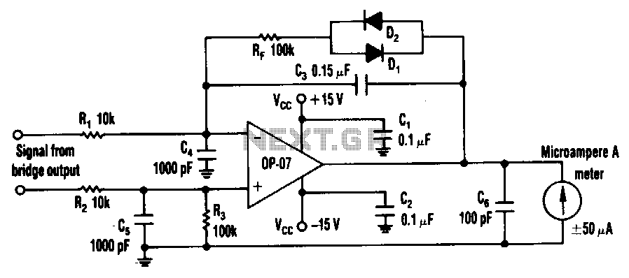
The circuit can utilize any general-purpose, low-offset, low-drift operational amplifier (op amp), such as the OP-07. The differential signal from the bridge feeds into an amplifier that drives a standard, rugged ±50 µA meter. However, near the null point, the significantly reduced signal level from the bridge necessitates very high gain to achieve high null resolution. To implement the variable-gain feature, the feedback path of the op amp requires a dynamic resistance that increases as the input signal decreases. Two common signal diodes, D1 and D2, are arranged in an antiparallel configuration within the feedback path to accommodate all positive and negative inputs. To stabilize the op amp circuit at high gain, capacitors C3, C5, and C6 are used to attenuate high-frequency response, while capacitors C1 and C2 serve to bypass the power supplies of the amplifier.
The described circuit employs an operational amplifier configured to amplify the differential signal from a bridge sensor. The choice of a low-offset, low-drift op amp, such as the OP-07, ensures minimal error and drift in the output signal, which is crucial for precision applications. The bridge sensor generates a differential output that is typically small, particularly around the null point. To enhance the sensitivity and achieve high resolution at this critical point, the circuit implements a variable gain mechanism. This is accomplished through a feedback network that adjusts the gain dynamically based on the input signal level.
The inclusion of diodes D1 and D2 in an antiparallel arrangement within the feedback loop is a strategic design choice that allows the circuit to handle both positive and negative signal excursions effectively. This configuration ensures that the feedback mechanism can adapt to the polarity of the input signal, maintaining linearity and stability across the operational range.
Capacitors C3, C5, and C6 play a vital role in stabilizing the op amp circuit, particularly when operating at high gain. These capacitors act as low-pass filters, reducing the circuit's response to high-frequency noise and preventing unwanted oscillations that could arise from the high gain settings. Additionally, capacitors C1 and C2 are essential for power supply bypassing, helping to filter out any noise present on the supply lines and ensuring a stable voltage is provided to the op amp.
Overall, the circuit is designed to provide high precision and stability in applications where small differential signals need to be accurately amplified, such as in sensor applications or precision measurement systems.The circuit can use any general-purpose, low-offset, low-drift op amp, such as the OP-07. The differential signal from the bridge feeds an amplifier that drives an ordinary, rugged ±50-p.A meter. Near the null point, however, the drastically reduced signal level from the bridge requires very high gain to achieve a high null resolution.
To provide the variable-gain feature, the op amp"s feedback path needs a dynamic resistance that increases as the input signal drops. Two common signal diodes, Dl and D2, in an antiparallel configuration in the feedback path supply function for all positive and negative inputs. To stabilize the op amp circuit at high gain, capacitors C3, C5, and C6 reduce response to high frequencies; capacitors Cl and C2 bypass the amplifier"s power supplies.