
Active crossover circuit with TL074

The Electronic Crossover Circuit is designed to effectively separate audio signals into different frequency bands, allowing for enhanced control over audio output in various applications. The use of a quad BIFET operational amplifier ensures low noise and high performance, making it suitable for professional audio environments. The gain stage provided by U1-a amplifies the incoming audio signal to a suitable level for processing.
The low-pass filter, constructed with resistors R4, R5 and capacitors C2, C3, works in conjunction with operational amplifier U1-d to allow frequencies below a certain cutoff to pass through while attenuating higher frequencies. Conversely, the high-pass filter, utilizing resistors R6, R7 and capacitors C4, C5 with operational amplifier U1-c, permits higher frequencies to pass while attenuating lower frequencies. The Butterworth filter design is particularly advantageous as it maintains a flat frequency response within the passband and offers a smooth roll-off beyond the cutoff frequency, minimizing phase distortion.
The balancing network, comprising resistors R8, R9, R10, R14 and potentiometer R11, allows for fine-tuning of the output signals. This feature is particularly useful in live sound applications or studio settings where precise control over audio levels is required. The unity gain bandwidth achieved when the potentiometer is centered ensures that both the high-pass and low-pass outputs are balanced, providing an optimal listening experience.
Power regulation within the circuit is achieved through the use of resistors R12, R13 and diodes D1, D2, which stabilize the voltage supplied to the operational amplifiers and filters. The decoupling capacitors C6 and C7 further enhance the stability of the power supply by filtering out any high-frequency noise, ensuring that the operational amplifiers function effectively without interference.
Overall, the Electronic Crossover Circuit is a critical component in audio processing, enabling the separation of audio frequencies for improved sound quality and control. Its design considerations, including the choice of filters and amplification stages, reflect a thorough understanding of audio engineering principles.An audio source, like a mixer, preamp, EQ, or a recorder, is fed to the input of the Electronic Crossover Circuit. This signal is either AC or coupling, depending on the setting of switch 51, the non-inverting input of buffer amplifier Ul-a, a section of a quad BIFET, low amp TL074 noise made by Texas Instruments op.
This stage has a gain of 2, and its output is distributed to both a low pass filter made by R4, R5, C2, C3, and Uld op-amp, and a high-pass filter made by R6, R7, C4, C5, and op amp ULC. These are12 dB / octave Butterworth filters. The response of the Butterworth filter was chosen because it gives the best compromise between the damping and phase.
The values of capacitors and resistors varies depending on the selected connection that your device works. The filter outputs are fed to a balancing network made by R8, R9, RIO, R14 and potentiometer RLL balance.
When the potentiometer is at its center position, there is a unity gain bandwidths for both high and low filters. Power for the electronic circuit is regulated by Crossover R12, RI3, Dl and D2, and decoupled by C6 and C7.
Related Circuits
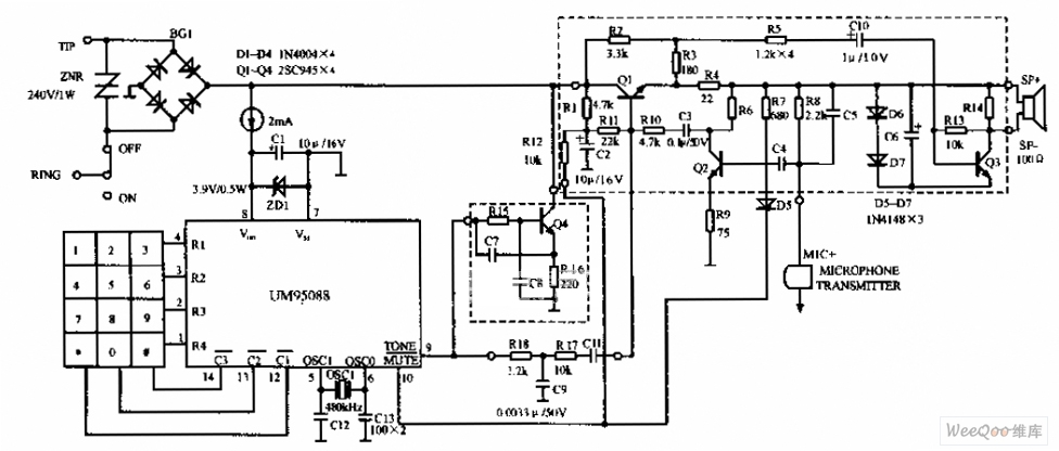
The UM95088 telephone circuit diagram is depicted in the image above. The UM95088 is a specialized integrated module designed for dual-tone multi-frequency (DTMF) telephone dialing. It utilizes CMOS technology and comes in a 14-pin dual-in-line package. The schematic for...
The NE5532 preamplifier is widely recognized for its excellent performance. It is now being utilized as a small power amplifier. While the general operational amplifier (op-amp) circuit remains similar, there are notable changes in some resistors and capacitors, leading...
A CI-22BG tube and a CI-3BG tube were purchased for a total of 16G. Due to the lack of radioactive materials for testing the Geiger counter, a piece of radioactive Fiesta dinnerware was ordered from eBay. Red Fiestaware historically...
This circuit is designed to connect stereo outputs from four different sources or channels as inputs, allowing only one of them to be selected and connected to the output at any given time. When the power supply is turned...
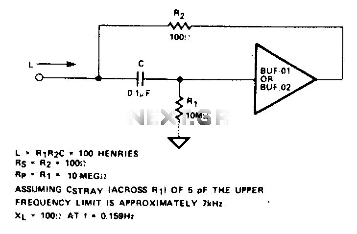
An active inductor is implemented using an eight-lead integrated circuit (IC), two carbon resistors, and a small capacitor. A typical commercial inductor with a value of 50 henries may occupy up to five cubic inches. An active inductor circuit provides...
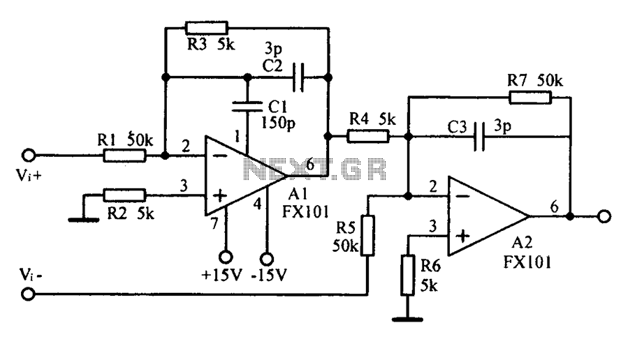
Common mode input voltage up to a difference of 100V enlarged circuit diagram. The circuit diagram described features a design capable of handling a common mode input voltage with a differential range of up to 100V. Such a configuration is...