
Active ferrite rod antenna for HF

The circuit features a red connector intended for an optional external antenna, which enhances signal reception capabilities. This connector is linked to the secondary winding of the circuit, allowing for effective signal amplification. The black connector serves as the ground wire, establishing a common reference point for the circuit and ensuring proper operation.
To improve the circuit's stability, particularly under high-gain conditions, two bypass capacitors rated at 100nF are incorporated into the design. These capacitors are strategically soldered from various +9V supply points to the ground plane. Their purpose is to filter out noise and provide a stable voltage supply, which is crucial for maintaining performance in sensitive electronic applications.
The ferrite component utilized in this circuit is the Amidon R61-050-300. Ferrite beads are often employed to suppress high-frequency noise and improve signal integrity. This specific ferrite is selected based on its impedance characteristics at the operating frequencies of the circuit, contributing to the overall reliability and efficiency of the design.
The integration of these components forms a cohesive unit that enhances the functionality and performance of the electronic circuit, ensuring it meets the demands of various applications while maintaining stability and signal quality.The red connector is for an optional external antenna wire and the black connector is for a ground wire. The red is wired to secondary winding and the black is connected to the circuit ground plane. Additionally two by-pass capacitors (100n) are soldered from different +9V locations to the GND plane for stability in high gain setting.
The ferrite is Amidon R61-050-300. Click the pictures. 🔗 External reference
Related Circuits
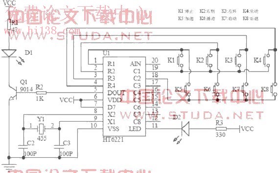
An infrared remote control car utilizes the AT89S51 microcontroller as the core controller. The system operates DC motors via L298 drivers, enabling manual control, autopilot, and tracking functions. The software is modular and developed using the C programming language....
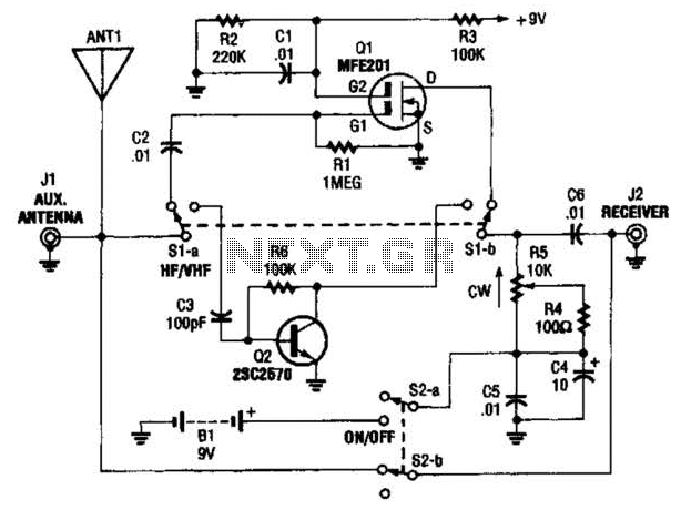
The AA-7 active antenna consists of two active components: Q1 (an MFE201 N-channel dual-gate FET) and Q2 (a 2SC2570 VHF silicon transistor), which form the foundation for two independent, switchable RF preamplifiers. The AA-7 active antenna is designed to enhance...
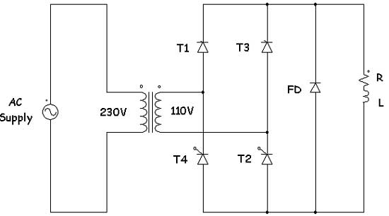
Controlled rectifiers are line-commutated AC to DC power converters that convert a fixed voltage and fixed frequency AC power supply into a variable DC output voltage. The input supply provided to a controlled rectifier is an AC supply with...
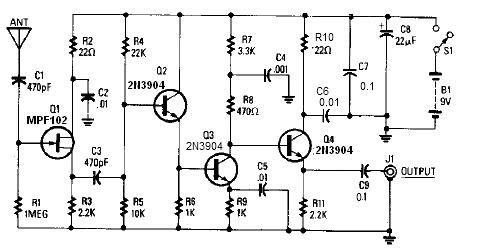
A simple active antenna can be designed using this electronic circuit diagram. This active antenna utilizes transistors and a few common electronic components. In the practice of short-wave frequency reception, a general rule is that a longer antenna will...
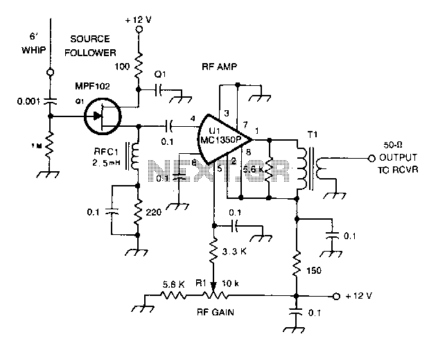
All capacitors in this circuit are disc ceramic. Fixed-value resistors are 1/4 or 1/2-W carbon. R1 controls the gain of U1. RFC1 is a miniature 2.5mH RF choke. More: T1 has 30 primary turns of #28 enamel wire on...
All ATL-3 loop windings are center-tapped and balanced with respect to their amplifier/receiver chassis ground, which leads to self-cancellation of electric field interference. Magnetic noise fields, such as those from televisions and electric meter boxes, or electromagnetically radiated interferences,...