
active loudness circuit schematic

The proposed circuit design involves a dynamic equalization system that utilizes a variable gain amplifier (VGA) in conjunction with a microcontroller for real-time adjustments. The microcontroller is programmed to interpret the position of the tone control knob and adjust the gain of specific frequency bands accordingly, based on pre-defined Fletcher-Munson curve data.
The circuit consists of an input stage where the audio signal is received, followed by the VGA, which is controlled by the microcontroller. The microcontroller processes the knob position using an analog-to-digital converter (ADC) and maps it to the corresponding gain settings for each frequency band. The output stage includes a low-pass filter to smooth the adjustments and prevent abrupt changes in audio quality.
The frequency bands can be divided into three primary sections: bass (20 Hz - 250 Hz), midrange (250 Hz - 4 kHz), and treble (4 kHz - 20 kHz). Each section has its own adjustable gain, allowing for a tailored audio experience that compensates for the listener's ear sensitivity at various volume levels.
Additionally, the circuit can incorporate a feedback mechanism that monitors the output audio signal, ensuring that the adjustments made by the microcontroller do not introduce distortion or unwanted artifacts. This feedback loop can enhance the overall performance of the audio system, providing a more refined listening experience regardless of the volume setting.
Overall, this approach not only simplifies the user interface by allowing a single control knob to manage complex adjustments but also ensures that audio reproduction remains consistent and pleasing across different listening environments.To get good audio reproduction at different listening levels, a different tone-setting controls should be necessary to suit the well known behavior of the human ear. In fact, the human ear sensitivity varies in a non-linear manner through the entire audible frequency band, as shown by Fletcher-Munson curves.
A simple approach to this problem can b e done inserting a circuit in the Preamplifier stage, capable of automatically varying the frequency response of the entire audio chain in respect to the position of the control knob, in order to keep ideal listening conditions under different listening levels. 🔗 External reference
Related Circuits
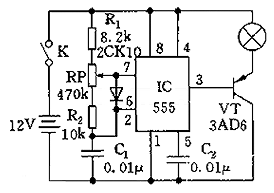
The circuit illustrated in the figure is a dimmer using the 555 timer as the core component. The 555 timer, along with resistors R1, RP, R2, and capacitor C1, forms an astable multivibrator. The oscillation frequency, f, is calculated...
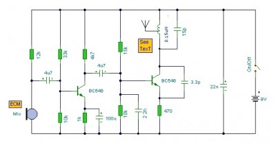
This is a mini FM transmitter circuit that utilizes two transistors. The audio sensitivity is notably high when paired with an ECM type microphone. The transmitter operates using a Hartley oscillator configuration. Typically, the capacitor in the tank circuit...
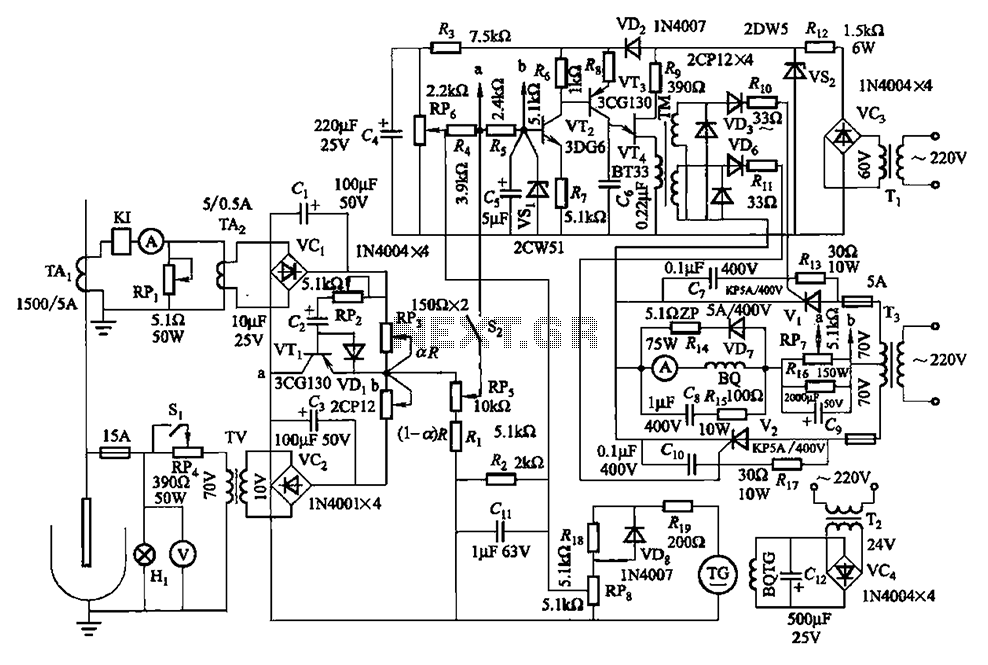
The circuit is illustrated in Figures 16-95 to 16-97. The electrode automatic adjuster demonstrates enhanced performance, featuring a high-accuracy, well-linear current output type bridge. Additionally, it incorporates a differential arc current negative feedback circuit (advanced) that allows for preemptive...
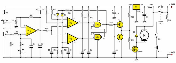
An electric scooter and E-Bike PWM speed controller circuit has been constructed. However, the oscillator is not functioning as intended. The printed circuit board has been checked and is confirmed to be in good condition, including all resistors. The electric...
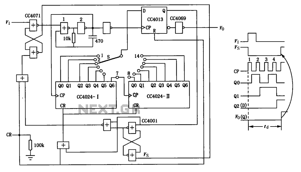
The circuit depicted in the figure is an optional delay circuit with a division factor. It consists of two 7-bit binary serial counters (CC4024) along with a controlled pulse source, which is composed of gate 1 and gate 2,...
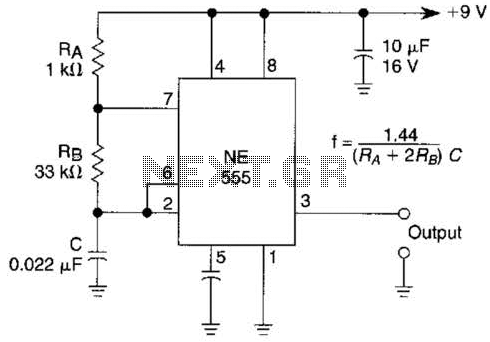
An astable multivibrator based on the 555 timer is presented. The frequency is approximately 975 Hz, determined by the values of RB and C. The astable multivibrator configuration using the 555 timer is a popular circuit for generating square wave...