
ADJUSTABLE SIREN

The described circuit utilizes an oscillator to generate sound waves at varying frequencies, which correspond to different tones of the siren. The multiposition switch allows for the selection of different capacitors, effectively altering the capacitance in the oscillator circuit. This change in capacitance directly influences the frequency output, thus enabling the user to adjust the tone of the siren to desired specifications.
The speed of the siren's wail is modulated by adjusting R3, a variable resistor. This adjustment alters the time constant of the RC (resistor-capacitor) network within the oscillator circuit, leading to changes in the frequency of the output signal. The inclusion of a 4700-ohm resistor in series with R3 serves a critical role; it prevents the siren from becoming inoperable when R3 is minimized. This ensures that even at its lowest setting, the circuit remains functional, providing a reliable operation.
Activation of the siren occurs via a momentary switch, which initiates the rising wail. The design allows for a user-friendly experience, as the siren can be easily engaged and disengaged. Upon pressing the switch, the oscillator begins to produce a sound that increases in pitch until the switch is released, at which point the sound diminishes until it reaches a cutoff point. This functionality is essential for applications requiring an attention-grabbing alert or warning signal.
The circuit's design is influenced by foundational principles in electronics, particularly in the areas of oscillators and sound generation. The choice of components and their configuration reflects practical considerations for achieving a robust and effective siren system. The reference to F. M. Mims' work indicates a source of further information for those interested in exploring similar projects or understanding the underlying concepts in greater depth.Tone is made adjustable by using multiposition switch to change capacitors in oscillator circuit. Speed (rate of change in frequency) of siren is adjusted with R3. 4700-ohm resistor in series with R3 keeps siren op-erational when R3 is rotated to minimum-resistance position. Siren is operated by pressing switch to produce rising wail, then releasi ng switch until wail drops down to cutoff. -F. M. Mims, "Transistor Projects, Vol. 1, " Radio Shack, Fort Worth, TX, 1977, 2nd Ed. , p 58-63. 🔗 External reference
Related Circuits
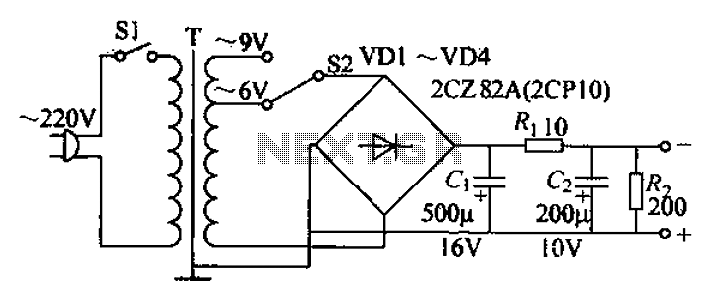
The adjustable current power supply circuit operates at 6V and 9V, utilizing a minimal number of components, which facilitates easy assembly. The circuit can deliver an adjustable output current of up to 100mA, serving as a suitable alternative to...

This low-cost operational amplifier circuit (A) generates four different functions with adjustable periods. For the components shown here, the period of the output waveforms is given by T = 4RC and T = 2RC. When switch SI is in...

An LM380 audio IC is configured as a feedback audio oscillator. A transistor astable modulates this oscillator at a low frequency, which produces a siren tone. The circuit utilizes the LM380, a power audio amplifier IC, which is configured to...
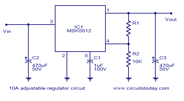
A reliable 10A adjustable voltage regulator based on the MSK5012, featuring an output voltage range of 1.3 to 30V. It is characterized by low ripple and high efficiency. The MSK5012 adjustable voltage regulator is designed for applications requiring a stable...

The circuit was designed to provide an adjustable power supply that is symmetrically configured, offering a voltage range from 1.25V to 30V at a current output of 1A. The adjustable power supply circuit is typically composed of several key components...

This circuit utilizes one of the LM389 transistors to control the power amplifier's operation by implementing a muting technique. The remaining transistors create a cross-coupled multivibrator circuit that regulates the frequency of the square-wave oscillator. The power amplifier functions...