
Advance Burglar alarm from dual-op amp

The burglar alarm system utilizes a dual operational amplifier (op-amp) to enhance its monitoring capabilities. The circuit typically consists of two main sections: the sensing unit and the alarm triggering unit.
The sensing unit employs a dual op-amp configuration to amplify signals from various sensors, such as motion detectors or door/window contacts. When a sensor is triggered, it generates a low-level voltage signal that is fed into the non-inverting input of the first op-amp. This op-amp is configured as a voltage amplifier, boosting the signal to a level suitable for processing. The gain of this amplifier can be adjusted by selecting appropriate resistor values in the feedback loop, allowing for customization based on the sensitivity required for the specific application.
The output of the first op-amp is connected to the inverting input of the second op-amp, which is configured as a comparator. This op-amp compares the amplified signal against a predetermined reference voltage set by a voltage divider circuit. If the amplified signal exceeds the reference voltage, the output of the comparator switches from low to high, triggering the alarm.
The alarm triggering unit may include additional components such as a relay or a transistor switch to activate a siren or notification system. The relay is typically connected to the output of the second op-amp, allowing it to control high-current devices while isolating the low-power op-amp circuit.
Furthermore, the circuit can include features such as delay timers, which prevent false alarms due to temporary disturbances, and reset mechanisms that allow the system to be easily rearmed after an alarm event. Overall, the use of a dual operational amplifier in a burglar alarm circuit provides enhanced sensitivity and reliability, making it an effective solution for security monitoring applications.Device such as burglar alarms and sirens, whose basic purpose is to monitor tested circuit diagram with description of burglar alarm alarm using dual operational amplifier. 🔗 External reference
Related Circuits
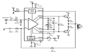
The LME49810 audio amplifier schematic is depicted in the accompanying circuit diagram. Based on the LME49810 datasheet, this component is a high-fidelity audio power amplifier driver intended for use in applications such as audio-video receivers, guitar amplifiers, powered studio...
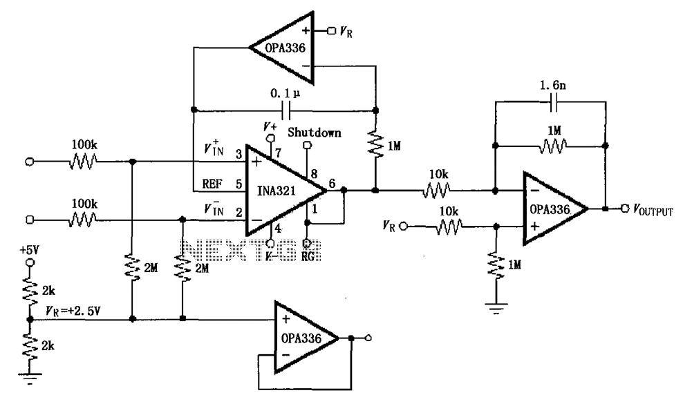
The INA321/322 forms a low-cost, medium-accuracy ECG amplifier circuit. The INA321 receives input signals from the patient's arm, amplifying them before sending the modified output to the operational amplifier OPA336. The OPA336 generates an output voltage from the inverting...
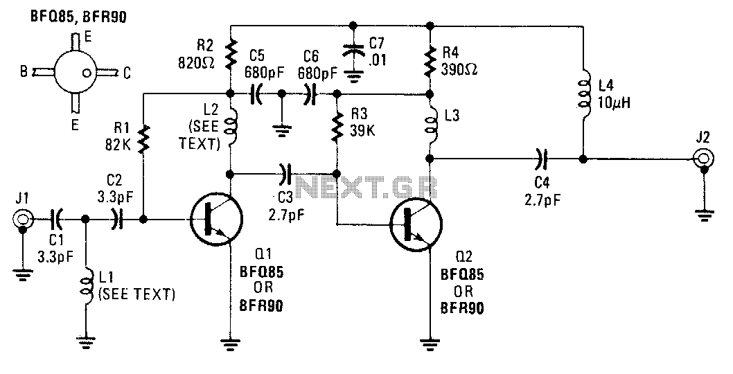
An inexpensive antenna-mounted UHF-TV preamplifier can add more than 25 dB of gain. The first stage of the preamplifier is biased for optimum noise performance, while the second stage is optimized for maximum gain. Additional details include Ll and...
A 2 x 18W Hi-Fi Stereo Power Amplifier is designed using two TDA2030 integrated circuits (ICs). This amplifier features good input sensitivity, low distortion, stable operation, and comprehensive protection against overloads and output short-circuits. It can serve as a...
The following two-transistor circuit is a preamplifier for magnetic phono cartridges, characterized by its frequency response defined by the RIAA standard for phono recording. This preamp circuit has a gain of approximately 40 dB (midband) at 1 kHz. The...
An amplifier is a device that accepts a varying input signal and produces an output signal that varies in the same way as the input but has a larger amplitude. The input signal may be a current, voltage, mechanical...