
Advanced Electronic Siren

The output stage of the oscillator consists of a BD 679 Darlington transistor with a piezo tweeter and 10mH choke in the collector lead. These two components form a resonant circuit at the frequency of operation, and without the correct value of choke, the output would not be nearly as high. The choke functions as a resistive path for the transistor when it is activated, allowing energy to flow through the coil and generate magnetic flux in the core. The transistor is driven by a square wave oscillator, which switches it off rapidly. The magnetic flux produced by the current through the coil collapses quickly when the current ceases, generating a high-voltage output across the coil that is of opposite polarity. Measured voltages can range from 70 to 120 volts, which is then directed to the piezo diaphragm, causing it to bend or "dish."
The piezo diaphragm acts similarly to a 30n capacitor, and energy discharges from it after a brief period to supply the choke. The behavior of voltage discharge from a capacitor resembles reversing the voltage direction, after which the transistor reactivates to restart the cycle. All components are designed to fit on a compact printed circuit board (PCB), necessitating the use of modern, small-sized parts to ensure compatibility. Resistors are specified as 1/4 watt, while electrolytic capacitors should have voltage ratings of 16V or 25V. Utilizing outdated or oversized components is discouraged as they will not accommodate the PCB design.
It is recommended to position components closely to the board to maintain a tidy appearance and to solder leads swiftly to prevent heat from traveling up the leads and damaging sensitive components. This is particularly crucial for the 100n mono-block capacitors, which have their leads soldered internally to a ceramic substrate using low-temperature solder that can be easily re-melted, compromising lead integrity. Care should also be taken with the transistor, as excessive heat can alter its characteristics, including gain.
In projects requiring an integrated circuit (IC), it is standard practice to install an IC socket, allowing for future inspection or replacement of the chip if needed. The socket features a cut-out that aligns with the overlay cut-out, aiding in correct chip orientation. It is advisable to delay fitting the chip until last, ensuring that the transistor is correctly oriented, as indicated by a thick line on the overlay that marks the metal side. Resistors, 1n and 100n capacitors, and the choke can be installed in either orientation since they are not polarity-sensitive. However, the 4u7 and 100u electrolytic capacitors must be installed with the positive lead inserted into the marked hole, with the negative lead identified by a stripe on the body.
The oscillation of voltage through the piezo diaphragm causes it to flex alternately in opposite directions, generating sound waves that are amplified by the cone shape of the piezo's mouth, enhancing the characteristic harsh sound. It is important to note that only one piezo can be driven by a single driver transistor, as the piezo and choke together create a resonant circuit, and connecting multiple piezos would disrupt the intended performance.Voltage is applied to the chip via pins 14 and 7 so that when power is applied to the project, the high and low frequency oscillators will come into operation to produce a wailing sound from the piezo. The high frequency oscillator is the only tone sent to the piezo. The low frequency oscillator merely modifies the high frequency by putting a varying "set on the 1n capacitor via the 1M so the frequency of the oscillator changes.
The low-frequency oscillator charges the 4u7 via the 1k and this voltage is passed to the 1n via the 1M. The best place to put the piezo is in the room you are protecting. The output stage of the oscillator consists of a BD 679 Darlington transistor with a piezo tweeter and 10mH choke in the collector lead. These two components form a resonant circuit at the frequency of operation and without the correct value of choke, the output would not be nearly as high.
The choke works by becoming a resistance path for the transistor when it is turned on and energy flows through the coil to create magnetic flux in the core. The transistor is driven by a square wave oscillator and it is switched off very fast by this type of waveform.
The magnetic flux produced by the current flowing through the turns in the coil collapses very quickly when the current stops and produces a voltage across the coil that is of opposite polarity and very high in amplitude. We have measured voltages of 70 - 120v and this voltage is passed to the piezo diaphragm to make it bend or "dish." The piezo diaphragm behaves exactly like a 30n capacitor and the energy flows out of it after a short period of time to feed the choke.
The action of voltage flowing out of a capacitor is exactly the same as reversing the voltage direction and a short time later the transistor turns on again to start the cycle again. All the components fit on a small PC board and you must use modern, small-size parts so that they fit on the board.
All the resistors are 1/4 watt and the electrolytics are 16v or 25v. Don't use old or large parts as they will not fit. Keep everything close to the board to make the finished product look neat and solder the leads quickly so that the heat does not run up the leads and damage the component. This applies especially to the 100n mono-block as the leads are soldered inside the capacitor to the ceramic substrate.
This is very low-temperature solder and can easily be remelted to make the leads weak or even fall off. You should also be careful with the transistor as excessive heat will change its characteristics, including its gain.
Always fit an IC socket to any project requiring a chip. This is standard practice with our kits as you may need to check the IC at some future date, if a fault occurs. A cut-out at the end of the IC socket corresponds to the cut-out on the overlay and this helps you fit the chip around the correct way.
Leave the fitting of the chip to last but make sure the transistor is around the correct way as the thick line on the overlay identifies the metal side of the device. The resistors, 1n and 100n capacitors and choke can be fitted around either way as they are not polarity sensitive.
The 4u7 and 100u electrolytics must be fitted so that the positive lead goes down the marked hole. You will find the negative lead is identified by a stripe down the side of the body of the electrolytic so that the other lead is positive. The action of voltage flowing in and out of the piezo diaphragm causes the diaphragm to firstly dish in one direction and then the other direction.
This movement creates sound waves that are reinforced (amplified) by the cone shape of the mouth of the piezo and this amplifies the characteristic harsh sound. You cannot drive more than one piezo from the same driver transistor as the piezo and choke form a resonant circuit and you will upset the performance.
🔗 External reference
Related Circuits
Jim Williams possessed a rare ability to combine his diverse talents in science, art, invention, and engineering. He created easily comprehensible tutorials, application notes, and technical phone conversations with customers, which facilitated improved designs in the field of electronics. Jim...
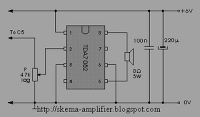
The TDA7052 is a mono output amplifier housed in an 8-pin Dual In-line Package (DIP). This device is specifically designed for use in battery-operated portable audio applications. Key features of the TDA7052 include the absence of external components, elimination...
This circuit generates a sound akin to a police siren. It utilizes two 555 timer integrated circuits (ICs) configured as astable multivibrators. The frequency is regulated by pin 5 of the IC. The first IC operates at approximately 1Hz,...
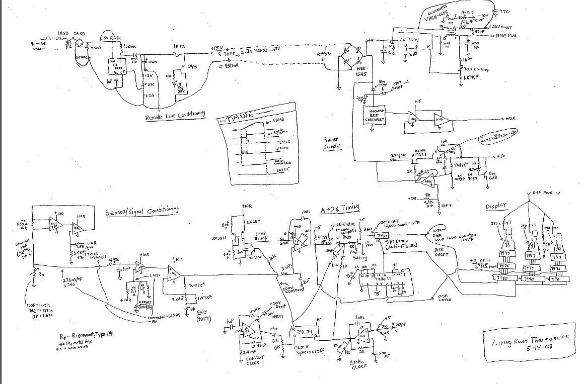
This circuit utilizes a +5 V reference output and an operational amplifier (op amp) to level shift and amplify the 2.1 mV/°C Tempco output into a voltage signal that varies with ambient temperature. Different scaling options can be achieved...
A schematic diagram of the oscillator is presented in Figure 1. The common-base transistor stage (Q1) amplifies the signal within the positive feedback loop. The positive feedback signal develops across the resistor R1, which is shared by the emitters...

The integrated circuit (IC) is a quad 2-input "AND" gate, specifically a CMOS 4081. These gates output a HIGH signal only when both inputs are HIGH. When the key connected to pin E is pressed, current flows through resistor...