
AFX Slot Car Lap Counter
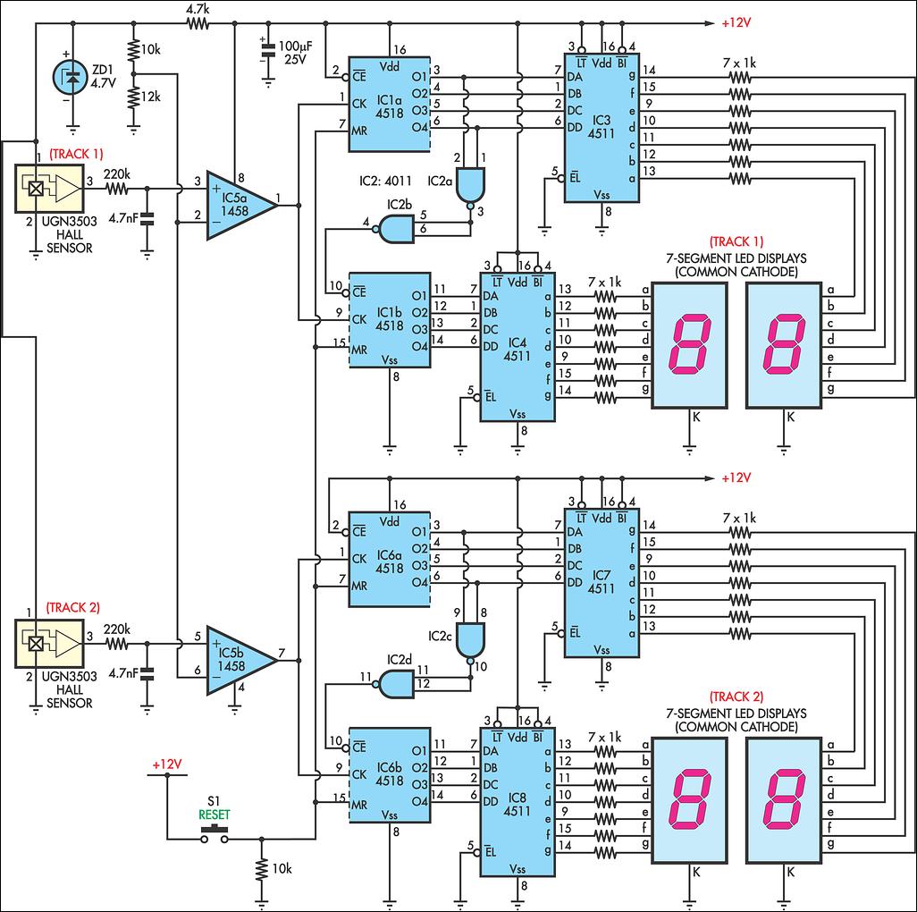
The circuit design for the AFX lap counter is structured to provide reliable counting functionality while maintaining simplicity. The Hall effect sensor (UGN3503) operates effectively in the specified configuration, detecting the magnetic field generated by the ground effects magnets in the slot cars. The sensor's output voltage shifts from 2V to 3V when a car passes over, providing a clear signal for counting.
The dual op-amp IC5 serves as the central processing unit for the sensor outputs, ensuring that both tracks can be monitored independently. The comparator configuration of IC5a and IC5b is critical, as it establishes a threshold for detecting the car's presence. The reference voltage of 2.5V is accurately set using the zener diode and resistors, creating a stable operating condition for the comparators.
When IC5a's output transitions high, it activates the 4518 BCD counter (IC1a), which is designed to count in binary-coded decimal format. The use of NAND gates (IC2a and IC2b) allows for seamless carry-out functionality, enabling the display of two digits. This modular design allows for the potential addition of more counters, accommodating longer races or multiple lanes.
The BCD outputs from IC1 are interfaced with 7-segment decoders (IC3 and IC4), transforming the binary-coded signals into a format suitable for visual display. The common cathode LED displays provide clear and bright visibility of the lap count, enhancing user experience during races.
The inclusion of a reset mechanism via push-button S1 is essential for race management, allowing users to easily reset the counters to zero, preparing the system for the next race. Overall, this circuit design combines functional components and thoughtful configuration to deliver an engaging and interactive experience for AFX slot car enthusiasts.AFX slot car sets are very enjoyable but you can increase the fun with a lap counter. This circuit will count from 00 to 99, with independent counters for each track. The sensing device used is a Hall effect sensor (UGN3503; available from Dick Smith Electronics). One of these sensors is glued under a section of each track (printed side up); betwe en the slot and one of the track rails is the best spot. In this position, it will allow the ground effects magnets on the cars to pass over them. The sensor will provide a voltage of about 3V when a car passes over it and about 2V without a magnetic field. Both counter circuits are identical, with dual op amp IC5 handling the signals from both sensors. IC5a and IC5b are wired as comparators, with a 2. 5V reference derived from zener diode ZD1 via the 10kO and 12kO resistors. Each time the output of IC5a goes high it clocks IC1a, a 4518 BCD counter. NAND gates IC2a & IC2b provide a carry out to the other half of IC1 for a 2-digit display. More counters may be cascaded this way to provide extra digits. The BCD outputs of IC1 drive 7-segment decoders IC3 & IC4 which drive common cathode LED displays. Push-button S1 resets the counters to 00 for both tracks for the start of a new race. 🔗 External reference
Related Circuits
The operation is completely safe due to protection against DC and AC short circuits between all pins and ground, thermal over-range conditions, load dump voltage surges up to 40V, and accidental open ground situations. The circuit design incorporates multiple safety...
This circuit utilizes a synthesized sound chip from Holtek, the HT-2811, which produces the sound of a "ding-dong" chiming doorbell. Additionally, it incorporates a CMOS 4026 counter display driver integrated circuit (IC) to tally the number of visitors. The...

This Spark Can Be Very DANGEROUS, So BE CAREFUL. WARNING: FAILURE TO DO SO: WILL CAUSE THE CASE OF THE COIL TO ALSO BE ELECTRIFIED! NOTE You MUST have a LOAD on the High Voltage Output. With NO LOAD,...
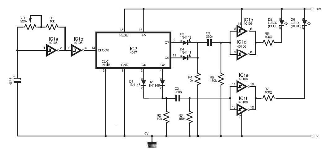
This circuit simulates the flashing lights of a police car, similar to those seen on British police vehicles. The operational amplifier IC1a functions as a square wave oscillator, with an adjustable frequency controlled by the variable resistor VR1 to...

The carbon dioxide (CO2) laser serves as a critical tool in high-tech industrial applications such as cutting and welding various materials, including metals. Smaller CO2 lasers are utilized for marking metals, wood, and composites, as well as in medical...
April 2006 marked the twentieth anniversary of the Chernobyl reactor accident. In the aftermath of the incident, winds dispersed much of the reactor's contents across central Europe, Scandinavia, and the UK. A large area surrounding the reactor remains restricted,...