
Air-Flow Sensing Thermistor Bridge

The thermistor-bridge circuit is an effective solution for monitoring the performance of cooling systems in various applications, including HVAC systems and electronic equipment cooling. The configuration consists of two thermistors, where one is directly exposed to the airflow and the other is shielded from direct air contact. This arrangement allows for the detection of temperature differentials that indicate airflow status.
The operational amplifiers (LM10C) are configured to provide constant current to the thermistors, ensuring that their performance is stable and reliable under varying temperature conditions. The LM311 comparator plays a crucial role in evaluating the voltage across the thermistors. When the airflow is adequate, the temperature readings from the thermistors will differ, resulting in an unbalanced voltage output that drives the comparator to a logical high state. Conversely, if airflow is obstructed, the exposed thermistor will reach the same temperature as the baffled thermistor, leading to a balanced output and a subsequent logical low signal from the comparator.
The inclusion of a 20-kOhm potentiometer allows for fine-tuning of the comparator's threshold level, enabling the circuit to be calibrated for specific airflow requirements. This feature is particularly advantageous in applications where varying environmental conditions may affect the cooling efficiency.
In practical implementation, the circuit can be integrated into a monitoring system that alerts operators to potential cooling failures, thereby preventing overheating and subsequent damage to system components. The thermistor-bridge circuit is a cost-effective and reliable method for ensuring optimal airflow in cooling systems, contributing to the longevity and efficiency of electronic devices and systems. Using the thermistor-bridge circuit, you can detect system-cooling air losses caused by filter or inlet blockage or fan failure. One thermistor is mounted directly in the air flow; the other is baffled. The exposed thermistor senses the temperature in the cooling system; the baffled thermistor senses the ambient temperature in still air. As long as the thermistors are at different temperatures, the bridge stays unbalanced and the circuit produces a logical high, indicating that the cooling system is working.
If the air flow stops, the exposed thermistor will reach ambient temperature, the bridge will become balanced, and the circuit will indicate ventilation-system failure by producing a logical low. The bridge circuit"s matched thermistors are biased by matched-current sources. Two LM10C operational amplifiers act as constant-current sources, and an LM311 comparator senses the difference between the voltage drops across the thermistors, producing the logical high when the bridge is unbalanced and the logical low when the bridge is balanced.
Use a 20-KOhmhm potentiometer to set the comparator"s threshold; this setting determines the minimum air flow that will cause the circuit to produce a logical high.
Related Circuits
It was previously assumed that dynamic braking would be most effective at higher speeds. However, tests conducted with a Faulhaber (Micro Mo) gear motor demonstrated that the brake could hold the motor almost stationary. These gear motors are constructed...
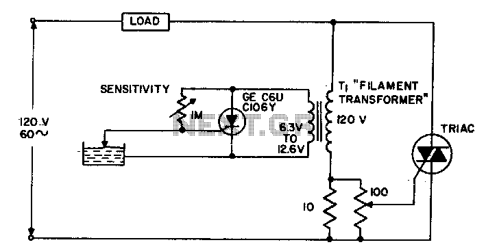
The circuit supplies power to the load until water conducts through the probe, allowing gate current to bypass from the low current SCR. This configuration provides an isolated low voltage probe to meet safety requirements. The described circuit operates as...
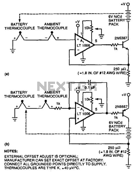
Two simple circuits enable NiCad battery charging based on the temperature differences between the battery pack and the ambient temperature. This method allows for fast charging by sensing the temperature rise that occurs after charging is complete when the...
This circuit controls a motor's rotation direction (clockwise or counterclockwise) using a potentiometer and can reduce the speed to zero when the potentiometer is positioned in the middle. The current is limited to 200 mA, and the voltage across...
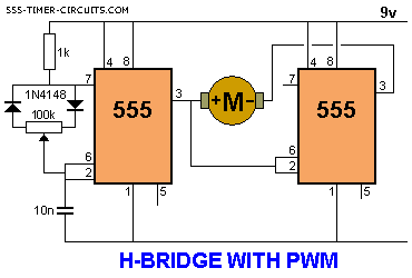
This H-bridge variant was one of the first in which the reversing circuitry is built into the driver, rather than (as is more-commonly done) into the control circuitry upstream of the driver. This is a handy circuit, though, for...
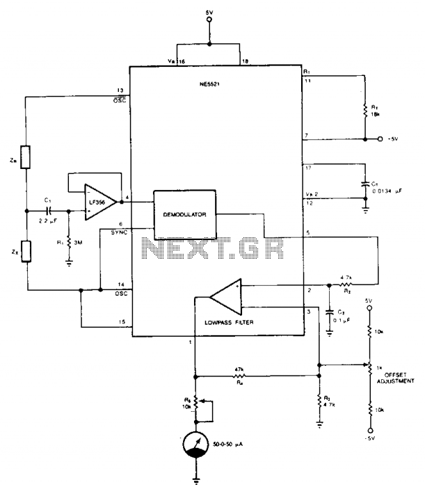
The circuit offers a straightforward and economical approach to matching resistors and capacitors. Impedances ZR and Zx create a half-bridge configuration, while OSC and OSC excite the bridge in a differential manner. An external op-amp, specifically a FET input...