
Alarm Circuits

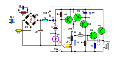
The high power siren circuit operates using a complementary push-pull configuration, which enhances efficiency and sound output. The BC557 transistor serves as the PNP component of the pair, while the BC337 functions as the NPN transistor. This arrangement allows for effective switching and amplification of the audio signal generated during oscillation.
Capacitor C2 plays a crucial role in the timing and frequency modulation of the circuit. Its charging and discharging characteristics directly influence the oscillation frequency. Resistor R8 is selected to control the discharge rate of C2, thereby affecting how quickly the circuit transitions from a low frequency to a high frequency and vice versa.
The circuit's functionality can be further refined by adjusting the values of the resistors and capacitors involved. This allows for customization of the siren's sound characteristics to suit specific requirements. Additionally, the use of a potentiometer in place of R8 can provide variable control over the discharge rate, enabling the user to fine-tune the frequency response dynamically.
Overall, this high power siren circuit is versatile and can be adapted for various applications, including alarms, warning signals, or other audio signaling needs. Properly designed, it can deliver a powerful and effective sound output suitable for demanding environments.High Power Siren Circuit This article is all about a comparatively strong siren circuit useful for any purpose. A complementary transistor pair (BC 557 & 337) is arranged as an oscillator, directly drives the speaker.
Transistor Q1(BC 557) is used to provide full charging of capacitor C2. When P1 is pressed, C2 discharges through R8 and the circuit starts oscillating at a low frequency that increases slowly until a high frequency steady tone is reached and it is kept. When P2 is released C2 starts discharging and and output frequency slowly decreases. When C2 is charged fully the circuit stops oscillations. Tips. Adjust the 🔗 External reference
Related Circuits
To increase the chances of observing the northern lights, the limitations of current aurora prediction methods can be circumvented by directly sensing the light emitted by the aurora. The Aurora Alarm is a device designed to achieve this goal...

This circuit is a laser alarm system similar to those depicted in various movies. It employs a laser pointer beam to secure valuables and property. When the beam is interrupted by a person, animal, or object, the resistance of...
This circuit is permanently connected to a mains socket for the trickle charging of Ni-Cd batteries. In the event of a power outage, the lamp automatically turns on. Alternatively, an alarm sounder can be selected instead of the lamp....
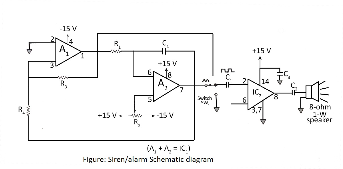
A simple siren or alarm circuit utilizing the MC1458 dual op-amp and the audio power amplifier LM380 is presented. The circuit diagram includes various configurations for sirens, doorbells, and alarm systems, along with a comprehensive parts list. The circuit operates...

The circuit utilizes a 555 integrated circuit (IC) functioning as an astable multivibrator. When a positive 9 volts is applied to pin 8, the circuit generates sound through a speaker. The connection to pin 8 is routed through a...

The SOS Alarm centralized control circuit is designed for use in calling a hospital bed and can also serve as an anti-theft alarm in multi-storey buildings, dormitories, warehouses, and similar locations. The circuit, as depicted in Figure 13-64, features...