
am radio

This AM radio circuit is designed to efficiently receive amplitude modulated (AM) signals while maintaining simplicity in its construction. The use of the BC 549 transistor as a high-gain preamplifier enhances the sensitivity of the receiver, allowing it to pick up weaker signals that a standard crystal radio might miss.
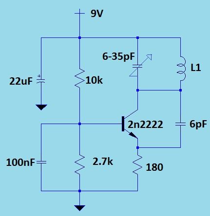
The circuit's design includes a few essential components: the BC 549 transistor, a variable capacitor for tuning, resistors for biasing the transistor, and the aforementioned coil. The coil's specifications are critical; it should consist of 60 turns of #26 enameled copper wire wound around a ferrite rod measuring 1 cm in diameter and 7.6 cm in length. This configuration creates a 200µH inductor, which is optimal for the frequency range of AM broadcasts.
Powering the circuit with a 9-volt battery provides sufficient voltage to operate the transistor in its active region, ensuring reliable amplification of incoming signals. The circuit can be tuned to different frequencies by adjusting the variable capacitor, allowing the user to select various AM stations.
Overall, this AM radio circuit exemplifies a balance between simplicity and performance, making it an excellent project for those interested in electronics and radio communications. The straightforward assembly and minimal component count make it accessible for beginners while still offering an engaging challenge for more experienced hobbyists.In previous article about how to make a radio we have discussed a simple crystal radio receiver circuit. The schematic mentioned here is also a simple AM radio circuit but it is not using a crystal, it is using high gain preamplifier stage of transistor BC 549.
The circuit is using only few components to make a good quality am receiver. For makin g 200uH coil take a #26 enameled copper wire and wound 60 turns on a 1cm diameter and 7. 6cm long ferrite rod. The circuit can be powered with a 9 volt battery. 🔗 External reference
Related Circuits
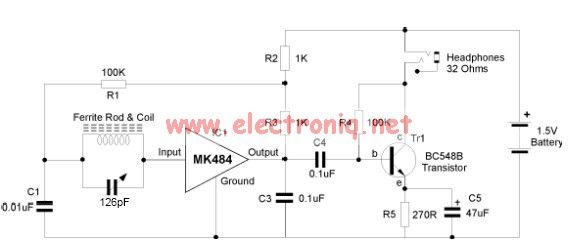
The MK484 AM radio circuit offers a comprehensive solution that includes an RF amplifier, detection, and automatic gain control (AGC) circuit. It requires only a few external components to achieve a high-quality AM tuner. The circuit features an input...
A typical RF amplifier is utilized in an AM radio receiver. In the schematic, the input circuit consists of the radio's antenna (L1, a coil), which is part of an LC circuit tuned to the desired station using a...
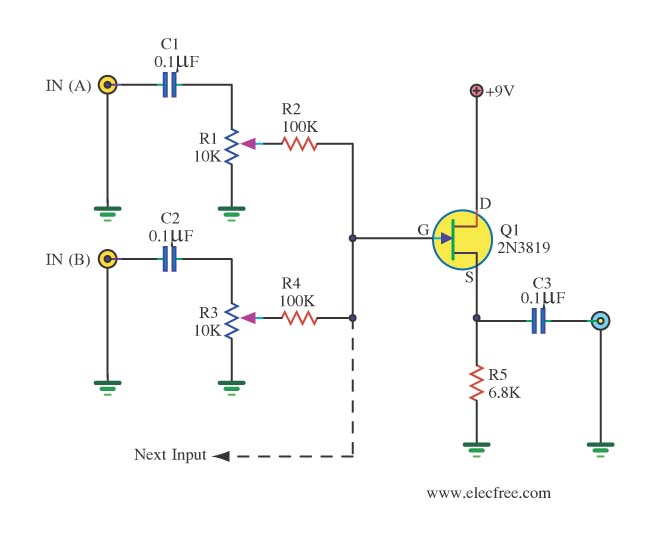
The audio from each radio will be connected to the iPod audio output and vice versa. This setup alters the impedance and can affect sound levels, potentially damaging the audio circuits of one or more radios involved. It is...
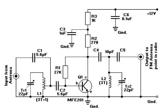
FM radio antenna amplifier circuit diagram. This amplifier will pull in all distant FM stations clearly. The active FM amplifier circuit is configured as a common-emitter tuned RF pre-amplifier wired around the VHF/UHF transistor MFE201. Below is a circuit...
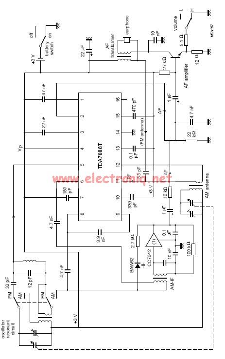
The TDA7088 features a frequency-locked-loop (FLL) system with an Intermediate Frequency (IF) of approximately 70 kHz. This circuit can be powered using a 3-volt battery cell or a regulated power supply. The TDA7088 is a highly integrated FM radio receiver...
This is not a cell phone jammer. Jamming a cell phone operates on similar principles, but requires a different construction, necessitating a frequency range from 800 MHz to 900 MHz. An operational amplifier and several other components are needed,...