
arduino dice

The project involves creating a digital dice using an Arduino microcontroller and a 7-segment display. The primary functionality allows the user to simulate the rolling of a dice by pressing and holding a button. When the button is released, the dice is "thrown," and a random number between 1 and 6 is generated and displayed on the 7-segment display. The animation of the shake and throw enhances the user experience, mimicking the traditional dice rolling process.
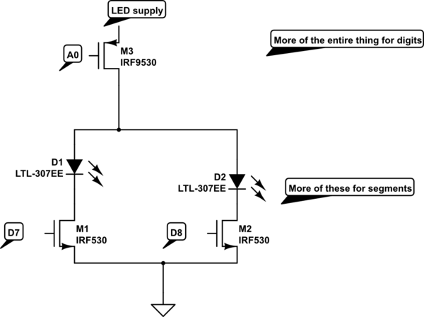
The circuit design includes the following components: an Arduino board (such as the Arduino Uno), a 7-segment display, a push-button switch, resistors for current limiting, and connecting wires. The 7-segment display is connected to the Arduino's digital pins to control each segment individually. The push-button switch is connected to another digital pin configured to detect the button press.
In the Arduino sketch, the program initializes the pin modes and sets up the display. A loop continuously checks the state of the button. When the button is pressed, the display shows a shaking animation, which can be achieved by rapidly cycling through a series of random numbers. Upon releasing the button, the program generates a random number between 1 and 6, which is then displayed on the 7-segment display, indicating the result of the dice throw.
This project not only serves as an engaging introduction to working with microcontrollers and displays but also provides insights into random number generation and user input handling in embedded systems. Proper attention should be given to the wiring and component specifications to ensure reliable operation.Arduino 7-segment display dice circuit and tutorial with Arduino sketch. Build a dice that is shaken by holding a button in and thrown by releasing the button. The shake, throw and number thrown are animated and displayed on a seven segment display.. 🔗 External reference
Related Circuits
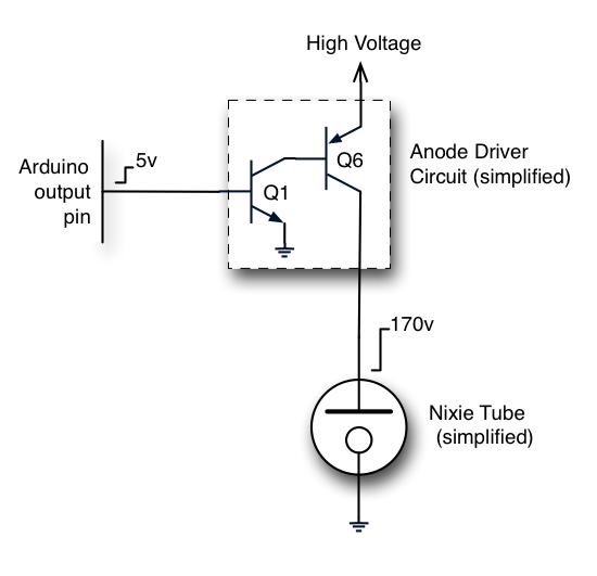
The Nixie tubes being utilized have 10 cathodes shaped like numerals and a screen-like anode. These are vintage Russian IN-12A tubes sourced from a reputable Ukrainian shop on eBay. Other types of Nixies may feature additional cathodes for displaying...
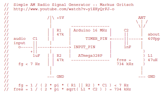
Markus constructed a software AM radio transmitter utilizing an Arduino. The audio signal is supplied to the ADC input via a decoupling capacitor. A PWM output pin directly controls a capacitor-inductor circuit connected to an antenna. The schematic and...
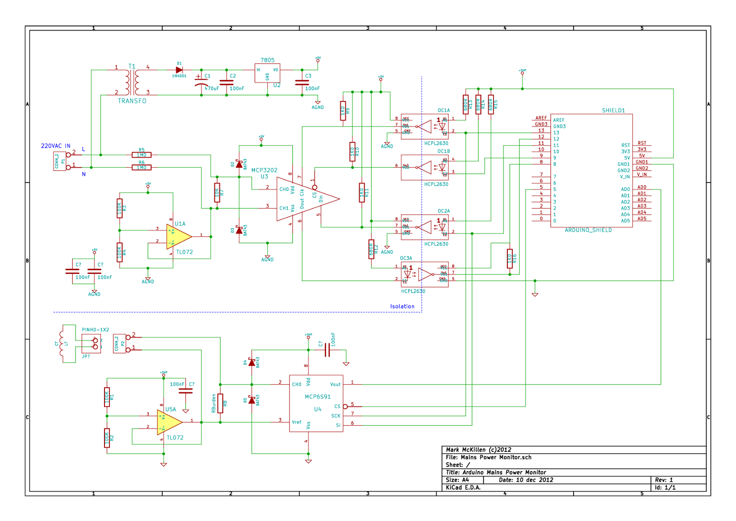
A mains (220-240VAC) power monitoring circuit has been sought for interfacing with an Arduino. While the OpenEnergyMonitor solution employs a transformer for isolation and measurement of mains voltage, it has been noted that the transformer does not couple effectively...
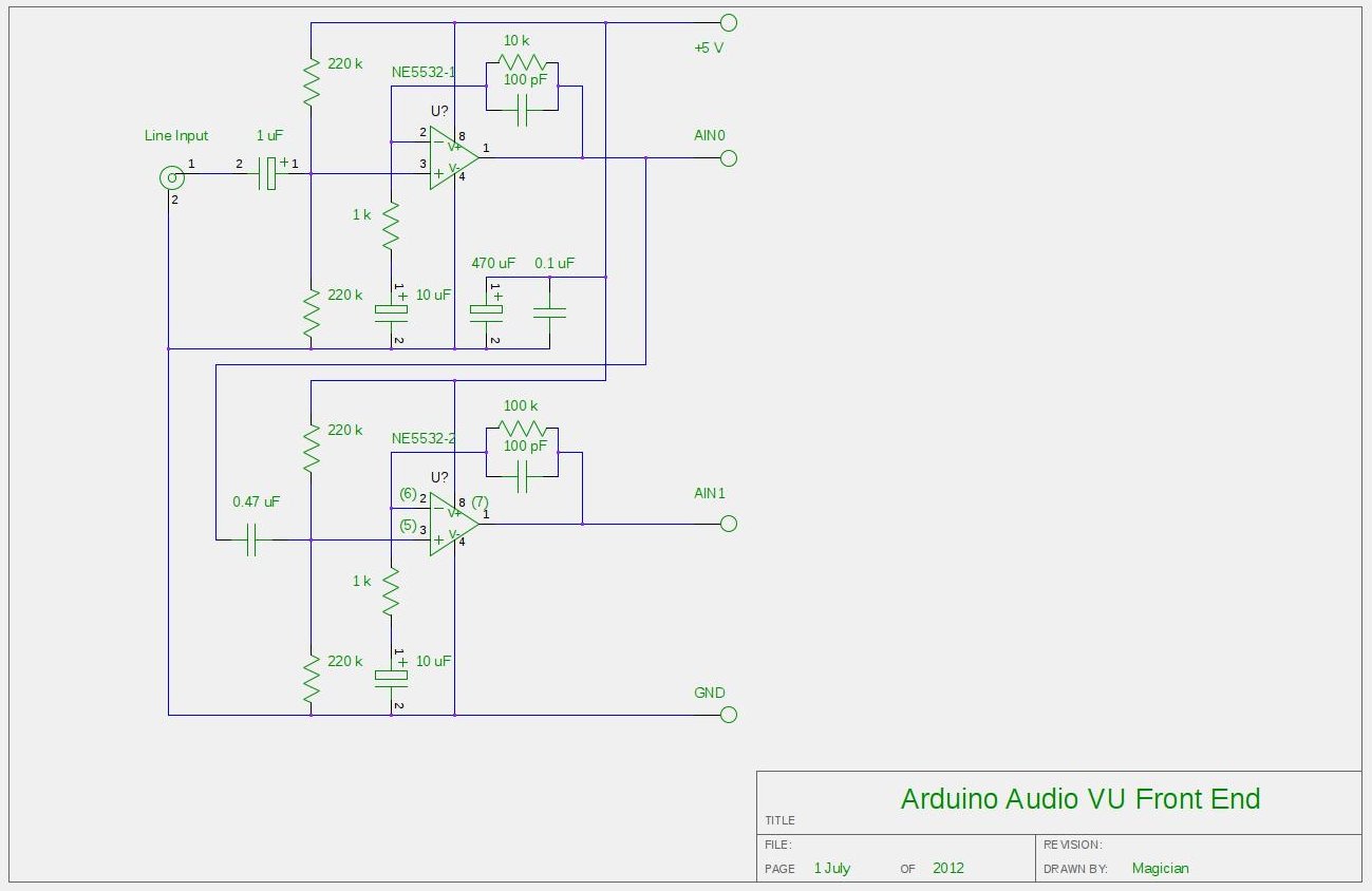
After experimenting with a stereo version of the VU meter described in a previous blog post, a studio-grade VU meter is now being presented. This meter features 24 steps, spaced equally every 3 dB, and covers a wide dynamic...
A scoreboard is located in the center of the room, which will be controlled from backstage. The scoreboard features two individual 3-digit numbers. Whenever the score changes, a sound will be emitted. The simplest, most efficient, and cost-effective solution...
An attempt at an Arduino guitar pedal. The guitar signal feeds through a PT2399 delay circuit, modified to include a JFET preamp phase. The delay circuit has Echo and Delay knobs. From there, it feeds into an optoisolated-Arduino-5V preamp,...