
ATMEL 89 Series Flash Microcontroller

The described programmer is a versatile tool for programming various Atmel microcontrollers, leveraging a straightforward design that incorporates standard TTL components for ease of assembly and cost-effectiveness. The interface with the PC's parallel port ensures compatibility with both modern and legacy systems, enhancing its usability across different environments.
In the circuit diagram, U1 acts as a data flow controller, facilitating communication between the PC and the microcontroller. The use of address latch components U3 and U4 enables precise control of the address lines, allowing for accurate data transfer during the programming process. The control signals generated by U2 are crucial for managing the programming sequence, ensuring that the microcontroller receives the correct instructions at the right times.
The power supply architecture is designed for reliability, with U6 providing a stable 5V logic supply essential for the operation of TTL components. U5's role in supplying the necessary programming voltage is critical, as microcontrollers often require specific voltage levels for programming. The choice of a wall adapter rated between 15 to 18V is practical, as it allows for a safe and efficient power supply that can accommodate variations in input voltage, while also ensuring that the output remains within the required operational parameters.
Adjustable components P1 and P2 are included in the design to facilitate voltage calibration, which is essential for maintaining the integrity of the programming process. The instructions for adjusting these potentiometers are straightforward, ensuring that users can achieve the required voltage levels without specialized equipment. The option to use either a crystal or a resonator adds flexibility to the design, accommodating different user preferences and component availability.
Overall, this programmer presents a well-thought-out solution for programming Atmel microcontrollers, balancing ease of use with the necessary technical specifications to ensure effective operation.This programmer was designed in view of to be flexible, economical and easy to built, the programmer hardware utilizes the standard TTL series parts and no special components are used. The programmer is interfaced with the PC parallel port and there is no special requirement for the PC parallel port, so the older computers can also be used with this programmer.
The programmer software supports the following Atmel devices AT89C51 AT89C1051 AT89C52 AT89C1051U AT89C55 AT89C2051 AT89S53 AT89C4051 AT89S8252 AT89C55WD Note: For 20 pin devices a simple interface adapter is required. The AT89C55WD has been included for testing purpose. Figure 1 shows the circuit diagram of the Flash Programmer, the programmer is interfaced with the standard parallel port of the PC.
As shown in the diagram U1 is used to control the data flow between controller and the PC, U3 latched the low order address byte and U4 latched the high order address byte, while U2 is used to generate the control signals for micro controller to be programmed. The power supply section uses U6 to generate the logic 5V supply while the U5 is used to provide the programming supply voltage to controller.
The power to the circuit is provided by a wall adapter of 15 to 18V output, normally a 15V type adapter will provide a 19~20V output voltage. As shown in the diagram the crystal X1 can be replaced by a resonator in that case capacitors C4 and C5 are not required, the pcb has the provision for both type of devices.
For the adjustment of P1 and P2 follow the steps shown below, 1. First adjust P1 to get the 12.75V at the output of LM317L regulator, make sure transistor T4 is off or temporarily connect the T4 base to ground. 2. Now temporarily short the collector of transistor T4 to ground. 3. Adjust P2 to get the 12.0V at the output of LM317L regulator. 🔗 External reference
Related Circuits
The JarLight is a compact flashlight utilizing a white light-emitting diode (LED) and powered by a single battery cell. This configuration allows for a highly compact design with significant light output and extended operational life, both for the battery...

This circuit utilizes a low-cost CMOS integrated circuit (IC) to control four light-emitting diodes (LEDs), turning them on and off at a frequency determined by the resistor values R1 and R2, as well as the capacitor values C1 and...
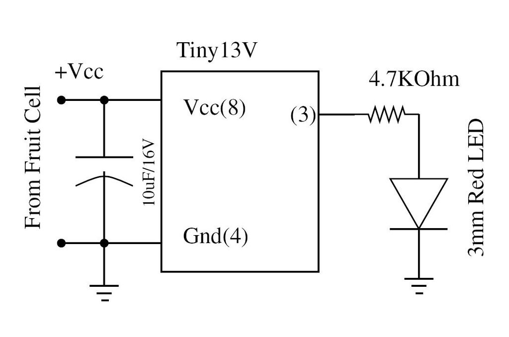
Wire the circuit diagram shown here on a breadboard. The choice of V type of AVR is important. For example, Tiny13V is very appropriate for such an application. To successfully implement the circuit diagram on a breadboard, several considerations must...
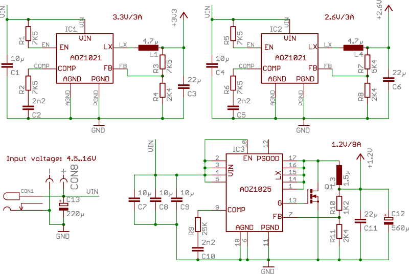
ZTEX USB-FPGA Boards require three different voltages: 1.2V, 2.5V-2.6V, and 3.3V, which must be supplied externally. This can be achieved using Power Supply Modules, Experimental Boards, or a user-specific design. To facilitate development in the latter scenario, three reference...
The following circuit illustrates the AT90LS2323 Microcontroller Circuit Diagram. Features include a voltage range of 2.7 to 6 volts, and compatibility with all 2323 chips. Components are included. The AT90LS2323 microcontroller circuit is designed to operate within a voltage range...
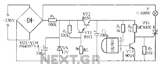
The H1.9811 single-channel flash control integrated circuit from Wuxi Love Core Microelectronics Co., Ltd. is designed for controlling flashing warning lights in road barricades. It features an integrated internal RC oscillator, frequency divider, output buffer amplifier, shaping circuit, and...