
Audio amplifier 2X18W

In bridge connection, as in the circuit, output power can reach 18W at a 4Ω load, with distortion at 0.5%, and power exceeding 20W with distortion near 10%, which is very suitable for automotive applications. The drive of amplifiers can be sourced from the output of existing amplifiers. A potentiometer may be needed in series to adjust the level to prevent distortion from overdrive. This particular circuit can also be utilized for other applications beyond automotive, such as driving small computer speakers. The amplifiers should be mounted on an adequate heatsink.
Part List
C1-2=220nF 100V MKT
D1-2=1N5408
F1=3A Fuse
C3-4=100nF 100V MKT
IC1-2=TDA1516Q
S1=2X2 SW
C5-6=2200uF 25V
M1-2=Speaker 30W/4Ω
The described circuit employs a bridge amplifier configuration using the TDA1516Q integrated circuit, which is designed for automotive audio applications. The TDA1516Q contains two amplifiers that can be configured in a bridge mode to increase output power while maintaining sound quality. The theoretical output power can be quadrupled when two amplifiers are used in this configuration, allowing for enhanced audio performance in vehicles where space and power are limited.
The circuit utilizes capacitors (C1, C2, C3, C4) for filtering and stability, ensuring that the audio signal remains clean and free from unwanted noise. The 220nF and 100nF capacitors are essential for coupling and decoupling stages of the amplifier, allowing for optimal frequency response. The use of large electrolytic capacitors (C5, C6) provides additional power supply filtering, which is crucial in automotive environments where voltage fluctuations can occur.
Diodes (D1, D2) serve as rectifiers, protecting the circuit from reverse polarity and ensuring that the amplifiers operate within safe voltage limits. The inclusion of a fuse (F1) is a safety feature that protects the circuit from overcurrent conditions, which could lead to component damage.
The output is designed to drive a 4Ω speaker (M1, M2), which is a common impedance for automotive audio systems. The circuit can deliver up to 18W at this load with minimal distortion, making it suitable for use in cars or as a compact audio amplifier for small speakers in other applications.
A switch (S1) allows for easy power control of the amplifier, enabling the user to turn the system on or off as needed. The potentiometer mentioned in the description can be incorporated into the circuit to adjust the input signal level, providing a means to prevent distortion caused by overdriving the amplifiers.
Overall, this circuit represents a practical solution for enhancing the audio output of car radios or other small audio applications while maintaining high fidelity and manageable distortion levels. Proper thermal management through heatsinking of the TDA1516Q is necessary to ensure reliable operation under load. In a lot of cars, the car-radios use amplifiers that their output power does not exceed the 5W with enough distortion in the limits of power. The problem is untied with the utilisation of external amplifiers, that will have the possibility giving much bigger power, with much smaller distortion.
With given the voltage operation of car that is + 12V, we do not have the possibility of taking power above a limit. The solution is we use two amplifiers in bridge connection, with result the output power quadruple, at least theoretically and in best, is doubled.
A opamp. that it will facilitate a lot in order to we materialise above, easy and with very few external components, is the TDA1516Q, that contain two amplifiers in a chip, with gain 20dB, has protection from overheat and short-circuit. In bridge connection, as in the circuit, we can have output power 18W in load 4R, with distortion 0.5% and power above 20W with distortion near in the 10%, power very good for the area of car. The drive of amplifiers can become from the exit of already existing amplifiers. May it need we interfere in series, a potesometer, with that we will adapt level in such level, so that we do not have distortion from overdrive.
The particular circuit can be also used for other uses except car, as drive small speaker computer. The amplifiers should be placed on a good heatsink. Part List C1-2=220nF 100V MKT D1-2=1N5408 F1=3A Fuse C3-4=100nF 100V MKT IC1-2=TDA1516Q S1=2X2 SW C5-6=2200uF 25V M1-2=Loundspeaker 30W/4ohm 🔗 External reference
Related Circuits
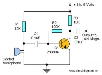
This straightforward circuit offers substantial amplification for weak audio signals, such as those from an electret microphone. It can be utilized in conjunction with an RF oscillator to create a highly sensitive RF transmitter. The audio microphone preamplifier circuit...
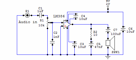
Here is a simple audio amplifier circuit that is easy to build and has few components. This circuit is built around the LM386 audio amplifier integrated circuit, useful when you need to power medium-sized speakers from a music player...
The circuit presented is experimental and should provide some fun to build and play about with. It has been built and tested and works very well indeed. Please note that it is a low current Class-A opamp and is...
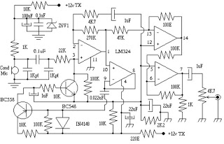
This circuit can be utilized in intercom systems, walkie-talkies, low-power transmitters, and packet radio receivers. Transistors T1 and T2 constitute the microphone preamplifier. Resistor R1 provides the necessary bias for the condenser microphone, while preset VR1 serves as a...
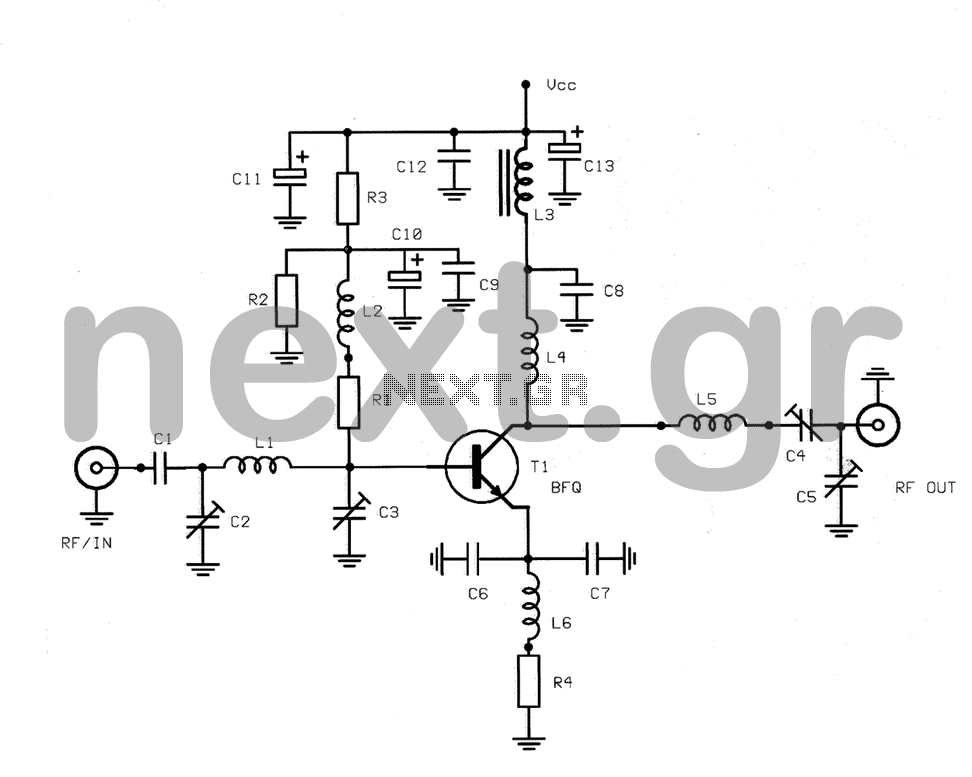
This structure is a radio frequency (RF) amplifier designed for small UHF TV transmitters, operating within the UHF channel range of 450-800 MHz. The amplifier enhances video signals in this frequency range and operates in Class A, utilizing the...
This guitar amplifier electronic architecture utilizes a robust conventional circuit design for the power amplifier, employing a single-rail supply of approximately 60V and capacitor coupling for the speakers. The advantages of this configuration for a guitar amplifier include a...