
Audio Beat Detect ?« Electronic Product Design
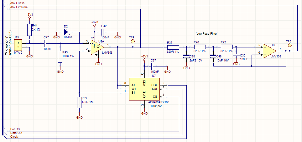
The circuit operates by utilizing a digital potentiometer, which is controlled by a microcontroller. This integration allows for real-time adjustments to the gain, ensuring optimal audio performance in varying ambient conditions. The microcontroller receives input from an audio sensor that detects the surrounding sound levels. Based on this input, it calculates the necessary gain adjustments and communicates with the digital potentiometer to modify the resistance, thus altering the gain of the audio signal.
For scenarios where automatic gain control is not required, a standard analog potentiometer can be substituted. This would allow for manual adjustments by the user, providing a more traditional interface for gain control.
The low-pass filter implemented in this circuit serves to eliminate high-frequency noise from the audio signal, enhancing the overall audio quality. The design is inspired by Graham Mitchell's solution, which is known for its efficiency and effectiveness in filtering unwanted frequencies. The low-pass filter typically consists of a resistor and capacitor (RC) configuration, which allows low-frequency signals to pass while attenuating higher frequencies. The cutoff frequency can be adjusted by changing the values of the resistor and capacitor, providing flexibility in the filter's performance.
In summary, this circuit combines advanced digital control with robust filtering techniques to create a versatile audio processing solution that can adapt to various environments while maintaining high audio fidelity.This circuit uses a digital pot to allow the microcontoller to automatically adjust the gain of the circuit to suit the ambient audio volume, but you could replace this with a standard pot if this isn`t needed. The low pass filter is a copy of Graham Mitchell`s nifty solution from this page: 🔗 External reference
Related Circuits
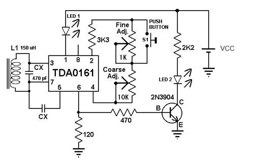
This metal detector circuit diagram utilizes the TDA0161 monolithic integrated circuit, which is designed to detect metallic objects by measuring variations in high-frequency Eddy current losses. The output signal is influenced by changes in supply current, which varies based...
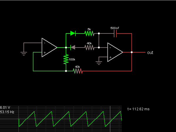
A step sequence can be applied that triggers every other step, allowing the activated steps to rise with each activation. This Low-Frequency Oscillator (LFO) can then be used to modulate other parameters of the plugin to enhance the sound....
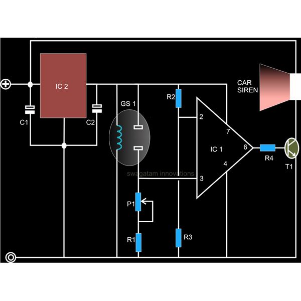
A straightforward smoke detector circuit has been presented through a schematic diagram, which can be easily constructed and installed in an area for essential detection purposes. The circuit utilizes the versatile FIGARO TGS 813 gas sensor as the primary...
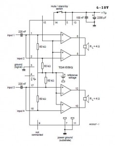
A 2x22 W car audio amplifier circuit utilizes the TDA1558, a monolithic integrated class-B output power amplifier that includes four 11 W single-ended amplifiers or two 22 W bridge-tied load (BTL) amplifiers. The TDA1558 is designed to drive speakers in...
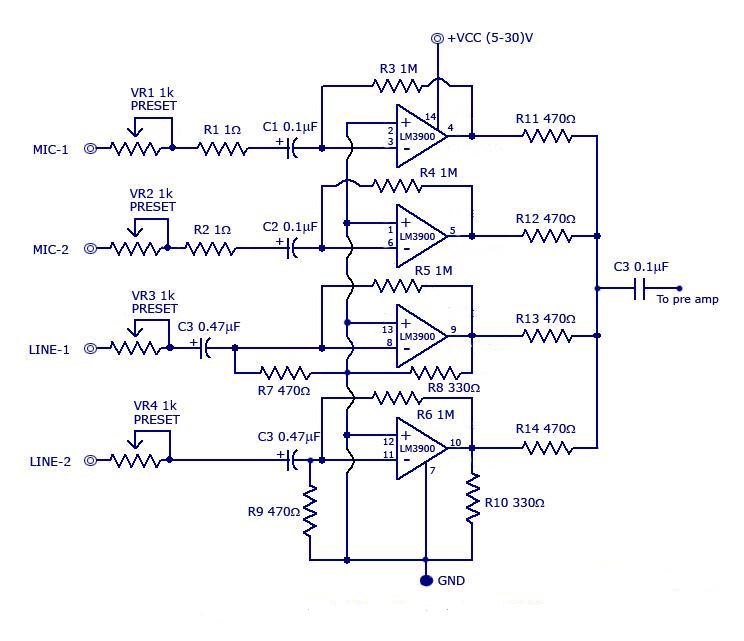
The circuit includes a quad channel amplifier (LM3900) with microphone audio inputs and direct line inputs. By adding circuits in parallel, the number of inputs can be increased for various applications. The input is connected to the inverting terminal...
This is an 8-input by 1-output audio/video switch module that can be controlled from a computer, such as through the parallel port. Each audio/video output can be switched to any of the 8 inputs independently. One module drives one...