
Audio isolation transformer

To construct an audio isolator using two audio transformers with a 1:1 transformation ratio, it is essential to select components that meet specific impedance requirements, typically greater than 1 kΩ. While high-quality audio transformers are available, they can be costly. An alternative is to utilize 600:600 ohm isolation transformers, which are more commonly found and suitable for less demanding multimedia applications, such as computer audio.
The assembly of the audio isolator involves connecting the primary side of each transformer to the audio source and the secondary side to the output connector. Using telephone line coupling transformers with a 600 ohm impedance is a practical choice, as they are widely used in high-speed modem applications and can provide adequate performance for general audio isolation.
When implementing the transformers, attention must be paid to the wiring configuration. Many transformers feature a marking on the coil indicating the start. Properly connecting the RCA connector's center wire to the coil start ensures that the audio signal is transmitted without introducing unwanted phase shifts. If the connections are reversed, a 180-degree phase shift may occur, leading to sound quality issues across the audio system.
Frequency response testing of the isolator can be conducted using an audio analyzer, such as the Nacamichi T-100. It is important to ensure that the audio isolation transformer does not introduce phase shifts that could affect the overall sound quality. For optimal performance, high-quality transformers such as the EOP Z1612 have demonstrated acceptable frequency response characteristics, maintaining ±1 dB from 40 Hz to 20 kHz, although performance below 40 Hz may be subpar. Caution is advised when selecting transformers, as lower-quality options may exhibit poor performance at higher frequencies, particularly above 5 kHz.If you want to build one yourself, you have to get two audio transformers which have 1:1 transformation ratio and greater than 1 kohm impedance. There are high quality audio transformers in the markes that meet those specs, but those can be quite expensive.
Another option it to use 600:600 ohm isolation transformers widely available for telecommunications and other uses. Those are not that high quality as good audio transformers, but can be well adequate for many not so demanding multimedia applications like computer audio if suitable transformer is selected.
I built some of my audio line isolators usign two high quality telephone line coupling transformers which have 600 ohm impedance (I built later some new ones using some high quality audio transformers). This is the most commonly transformer type used in high-speed modems. Best of those are quite wideband devices (far more bandwidth than usual 300-3400 Hz as used in telephone).
Using two of those transformers and few RCA connectors made quite satisfactory (but not really hifi) audio isolator. The connection is easy: connect primary side of the transformer to one audio connector and secondary to other.
The frequency measurements were made with Nacamichi T-100 Audio Analyzer and the isolator circuit was connected between it's 600 ohm output and 50 kohm input. I don't know if EOP Z1612 transformers are still available at Farnell, but you can try. If you are looking for other high quality transformers which could be a used, I would try ETAL P2001.
I haven't been able to test their performance in this application, but they have proven to good transformers in other laboratory test and applications. Avoid cheapest telephone and audio transformers, because their performance is very poor at frequencies over about 5 kHz (for example Radio Shack (273-1374)).
Notice one thing in the transformer wiring: Many transformers have the coil starting marked with dot. If you put the audio signal to the transformer in such way that the center wire in RCA connector is always connected to the coil end marked as coil start you will get a nice isolator.
If you for some reason connect the wires in one side of the transformer in the wring way, your transformer will cause a 180 degree phase shift to your audio signal. If some of the signals in your audio system will get this kind of phase shift and some other will not, you will face all kinds of sound quality prolems.
If you have this kind of system, it is best to test that the audio isolation transformer will not cause unitended phase shift to the signal. I used EOP Z1612 transformers in my test circuit and got quite acceptable frequency response of +-1 dB from 40 Hz to 20 kHz as you can see in figure below.
The bass frequency below 40 Hz is not good. 🔗 External reference
Related Circuits
Additionally, it may be necessary to include another input capacitor to mitigate high-frequency noise, although this is not directly related to the main question. The objectives are to achieve a voltage output of 0 - 12 V with a...
An average ability amplifier characterized by acceptable overall quality, while being simple in construction. It is frequently used in live loudspeakers. The design incorporates high-quality FET transistors, specifically HEXFET technology, which are voltage-controlled rather than conventional bipolar transistors. The...
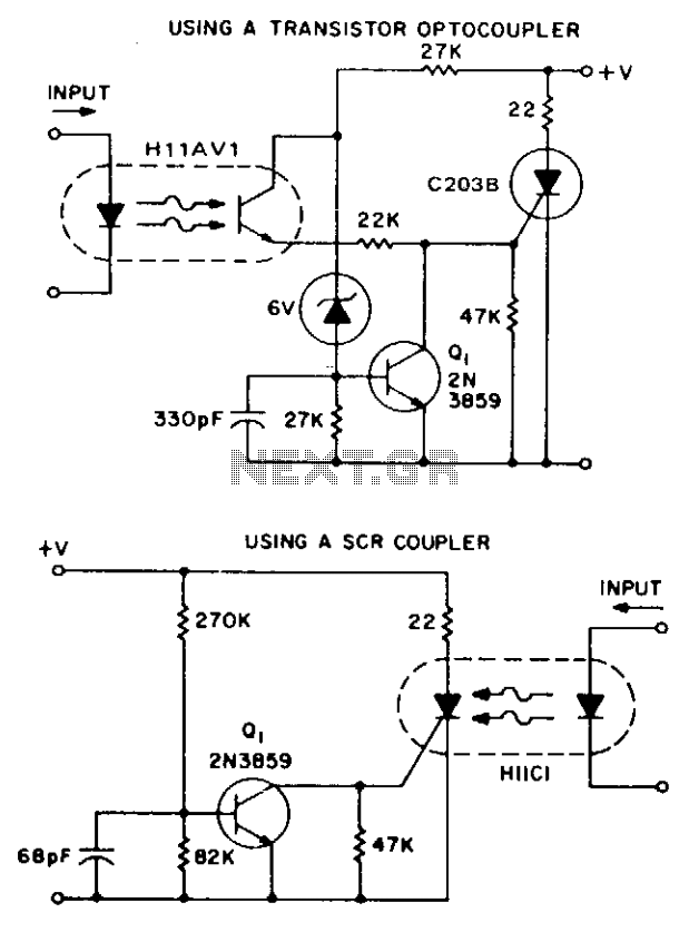
These two simple circuits provide zero voltage switching. They can be used with full wave bridges or in antiparallel to provide full wave control and are normally used to trigger power thyristors. If an input signal is present during...
The broadband amplifier NE592 can be used also for building a simple selective audio amplifier. By means of the +6 V and +12 V supply voltages, a DC coupling between the product detector and the AF amplifier is possible....

Band-pass filter used for a single channel, fH 50Hz, fL 13kHz. A band-pass filter (BPF) is an electronic circuit that allows signals within a specified frequency range to pass through while attenuating signals outside that range. In this case, the...
This project involved the design of an audio amplifier capable of delivering substantial output power with minimal component count while maintaining high quality. The power amplifier section utilizes three transistors along with a few resistors and capacitors in a...